![]()
Back to the Future
The Tuna Tin 2
by Doug Hendricks, KI6DS
![]()
The Tuna Tin 2 was originally designed by Doug DeMaw, W1FB in 1976. It appeared in QST, and was subsequently built by hundreds of QRPers, who were attracted to the project by the relatively easy parts availability. In fact, at the time of publication of the article, you could stop by the local Radio Shack and pick up everything needed except for the crystal.
When I looked at the article in the summer of 1996 and decided to build another Tuna Tin 2, I discovered that all of the parts were not available from Radio Shack. I contacted Dave Meacham, W6EMD, and he agreed to look at the article and update the parts to modern, available parts sources. Because we were changing the physical size of some of the parts, it meant that a new board would have to be layed out. That was to be my contribution to the project. The board was layed out and the new schematic drawn with Circad which is available free on the internet at http://www.holophase.com . The free version is demo version that is not crippled and is very useful for the average ham. You have the ability to printout circuit board patterns to a laser or inkjet printer with the demo version. About the only way the demo version differs from the full version is in the ability to generate Gerber files and PCX output. Holophase even has a special price for hams, $295 vs. $995 for non-hams. Contact them for details.
Circuit Details:
W1FB did a great job describing the circuit, so I decided to use his description from page 15 of QST, May 1976.
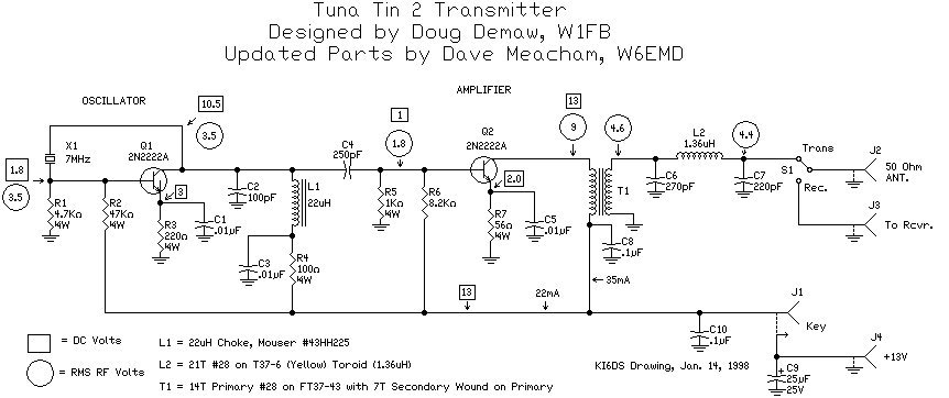
A look at the schematic will indicate that there’s nobody at home, so to speak, in the two-stage circuit. A Pierce type of crystal oscillator is used at Q1. Its output tickles the base of Q2 (lightly) with a few milliwatts of drive power, causing Q2 to develop approximately 450 milliwatts of dc input power as it is driven into the Class C mode. Power output was measured as 350 milliwatts (1/3 W), indicating an amplifier efficiency of 70 percent.
The collector circuit of Q1 is not tuned to resonance at 40 meters. L1 acts as a rf choke, and the 100 pF capacitor from the collector to ground is for feedback purposes only. Resonance is actually just below the 80 meter band. The choke value is not critical and could be as high in inductance as 1 mH, although the lower values will aid stability.
The collector impedance of Q2 is approximately 250 ohms at the power level specified. Therefore, T1 is used to step the value down to around 60 ohms (4:1 transformation) so that the pi network will contain practical values of L and C. The pi network is designed for low Q (loaded Q of 1) to assure ample bandwidth on 40 meters. This will eliminate the need for tuning controls. Since a pi network is a low-pass filter, harmonic energy is low at the transmitter output. The pi network is designed to transform 60 to 50 ohms.
L1 is made by unwinding a 10 uH Radio Shack choke (No. 273-101) and filling the form with No. 28 or 30 enamel covered wire. This provides an inductor of 24 uH. [Note: this part is no longer available from Radio Shack, so W6EMD subbed a 22 uH inductor here.] In a like manner, unwind another 273-101 so that only 11 turns remain, (1.36 uH). The 11 turns are spaced 1 wire thickness apart. Final adjustment of this coil (L2) is done with the transmitter operating into a 50 ohm load. The coil turns are moved closer together or farther apart until maximum output is noted. [Again, this part is not available, so W6EMD subbed a toroid, T37-6 (yellow) with 21 turns of #26 wire.] The wire is then cemented into place by means of hobby glue or Q dope. Indications are that the core material is the Q1 variety (permeability of 125), which makes it suitable for use up to at least 14 MHz.
T1 is built by removing all but 50 turns from a Radio Shack No. 273-102 rf choke (100 uH). The ferrite core in this choke seems to be on the order of 950, in terms of permeability. This is good material for making broadband transformers, as very few wire turns are required for a specified amount of inductance, and the Q of the winding will be low (desirable). A secondary winding is added to the 50-turn inductor by placing 25 turns over it, using #22 or #24 enameled wire. The secondary is wound in the same rotation sense as the primary, then glued into position on the form. Tests with an RX meter show this to be a very good transformer at 7 MHz. There was no capacitive or inductive reactance evident. The primary winding has an inductance of 80 uH after modification. [Although the RS 273-102 is still available, W6EMD also replaced it with a toroidal transformer, as it just looked better and as long as you have to wind a toroid, you might as well wind two.]
Increased power can be had by making the emitter resistor of Q2 smaller in value. However, the collector current will rise if the resistor is decreased in value, and the transistor just might "go out for lunch," permanently, if too much collector current is allowed to flow. The current can be increased to 50 mA without need to worry, and this will elevate the power output to roughly 400 mW.
One of the goals of this project was to provide readily available parts plus an easy source for circuit boards. I layed out the board and sent the artwork to Fred Reimers at FAR Circuits, 18N640 Field Court, Dundee, IL 60118, who is making boards available for $5 plus $1.50 shipping and handling for up to 4 boards.
I suggest that you do the metal work on your chassis before you start stuffing and soldering the parts on the board. You will first have to drill a hole to accommodate the connector that you have chosen for your key jack. You may use 1/8", 1/4" or phono here. The choice has been left to the builder. But whatever connector you choose, make sure that it is mounted in the center of the rectangle shown for J1, as J1 must be insulated from ground, as it is the means for applying 12V to the circuit. 12V is connected to one side of the jack, and when the key is closed, the resulting short circuit connects the 12V to the circuit.
W1FB wired his Tuna Tin 2 on a chassis made from a Tuna can, and I suggest that you do the same. He mounted his on the bottom, using a set of nibbling tools to cut all but about 1/4" of the bottom out, leaving the 1/4" rim to solder to. I decided to mount my board on standoffs that are connected to the bottom of the can and hold the board up to the edge of the rim. I then was able to put rubber feet on the bottom of the can. If you chose my method of mounting, you will need to drill 3 mounting holes in the board and then matching holes using the board as a template.
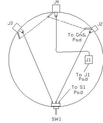
After you drill the mounting holes in the base, you will need to drill the holes for the 3 phono connectors and the SPDT toggle switch in the sides of the can. I mounted the Switch directly opposite the middle connector, and mounted the three connectors on the same side of the can about 1 1/4" apart. See Fig. 1 for a diagram that shows the placement of the connectors and the switch. W1FB chose to put his switch between the antenna and the receiver connectors, but I thought that I would like to have the power and antenna connectors on the back of my rig and the antenna switch on the front.
Next wire the chassis as shown in the diagram. I used pieces of wire about 4" long to make the connections between the connectors and the board. See Fig. 1 for the wiring diagram.
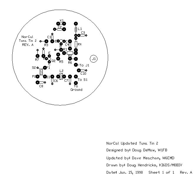
You are now ready to install and solder the parts. Refer to the parts list and the layout in Fig. 2. Be sure to check the schematic too. When you have finished, you are ready for the smoke test. Apply 12V power to the power connector, hook up a dummy load or 40 meter antenna to the rig, connect a key to the key jack, switch to transmit, and hit the key. You should hear a tone in a nearby receiver that is tuned to the frequency of your crystal.
If you have trouble getting your rig to work, DeMaw even had a trouble shooting section to his original article that is repeated here from page 16, QST, May 1976.
The voltage shown in the schematic will be helpful in troubleshooting this rig. All dc measurements were made with a VTVM. The rf voltages were measured with an rf probe and a VTVM. The values may vary somewhat, depending on the exact characteristics of the transistors chosen. The points marked 1 and 2 (in circles) can be opened to permit insertion of a dc milliammeter. This will be useful in determining the dc input power level for each stage. Power output can be checked by means of an rf probe from J2 to ground. Measurements should be made with a 51 or a 56 ohm resistor as a dummy load. For 350 mW of output, there would be 4.4rms volts across the 56 ohm resistor.
Operating voltage for the transmitter can be obtained from nine Penlite (AA) cells connected in series (13.5 volts). For greater power reserve one can use size C or D cells wired in series. A small AC operated 12 or 13 volt regulated dc supply is suitable also, especially for home station work.
I would like to thank all of the NorCal members who helped with the updating of the Tuna Tin 2 transmitter, Dave Meacham, W6EMD for doing the engineering, Dave Adams and Gary Diana for providing prototype work, Brad Mitchell, Jerry Parker and George Heron for Web page production. It is the first in a series of old time rigs that will be updated by NorCal. We will also do the Herring Aid 5 Receiver, the Chopped Beef VFO, and the Codzilla Amp, all updated with modern available parts and circuit boards, but still keeping the flavor of the original design. I hope that you build and operate these rigs.
72, Doug, KI6DS
Return to the "Back to the Future" page
![]()
![]()
![]()
![]()