![]()

![]()
Assemble your Fireball 40 QRPp Transmitter Kit by following this step-by-step photographic description. (Be sure to also follow the complete notes supplied in the FB40 Tech Manual, downloadable in PDF format from this site.)
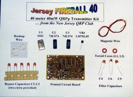
Lets take a look at the parts supplied in the kit ... not to many parts, really, all layed out in front of you. Locate everything in your bag o' parts and compare them to this and following pictures.
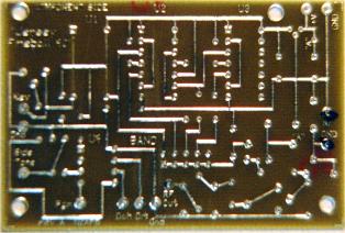
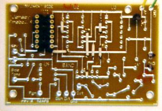
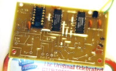
Close-up on the printed circuit board (TOP) ... even though there are pc traces here, you'll put the components on this side.
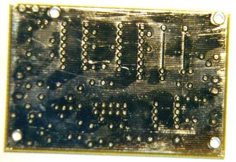
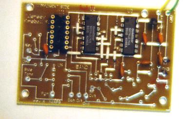
Close-up on the printed circuit board (BOTTOM) ... you'll solder most component leads from this side. Be careful to use a fine pointed soldering iron, as there is not much clearance between the pads and the ground plane.
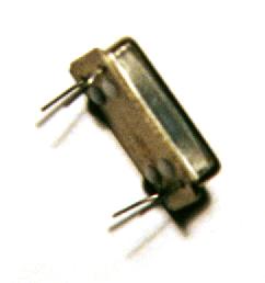
The Oscillator "Can": U1 ... this is the heart of the transmitter. This little metal can is a TTL oscillator supplying a 28.322 MHz signal to the rest of the circuits on the board. You'll notice that this device has only 4 pins or wires. Pin 1 is denoted on the top of the package with a dot in its corner ... this pin will ultimately be inserted into the square pad pin 1 in the U1 position on the circuit board.
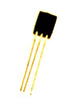
The Voltage Regulator: VR1 ... this little transistor-like device in a TO-92 package is an LM78L05ACZ voltage regulator providing 5V to the transmitter circuits.
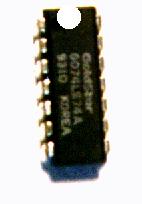
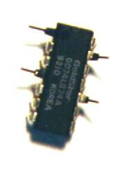
The Flip-Flop Dividers: U2 and U3 ... this photo shows the 74LS74 integrated circuit used to divide the 28.322 MHz oscillator signal in half 3 times to produce signals on the 20m, 40m and 80m bands.
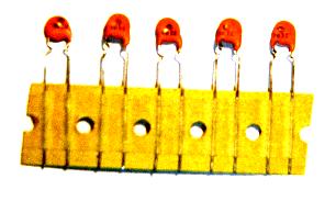
Bypass Capacitors: C1-C3 ... these capacitors are used to decouple the +5V power bus and stabilize the circuits. You'll use three of these caps, and 2 extra are provided in the kit.
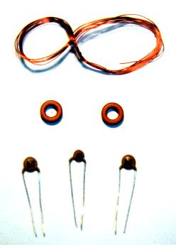
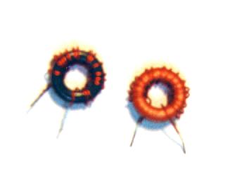
Low Pass Filter Components: L1, L2, C4-C6 ... you'll be winding 16 turns of the magnet wire around each of the toroid cores (the little donut-shaped parts) to create 1 microHenry inductors. The capacitors complete the low pass filter. C4 and C5 are on the outside (labeled "820") and the middle capacitor is C6 (labeled "102").
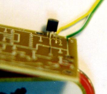
The voltage regulator VR1 is soldered to PCB ... carefully insert the VR1 device oriented as shown in the parts layout diagram, with the flat side toward the center of the board.
Soldering VR1 to the bottom of the board ... with a fine point soldering iron, carefully solder the device leads to the pads. Also insert and solder the wires supplying the 9-14V power supply to the board. As the manual instructions state, be sure to bend the negative wire over after passing it through the GND pad and solder it to the pad and to the ground plane.
Putting in the jumpers ... you'll be putting in seven jumpers on the top of the circuit board, at the positions noted with the thick lines in the Parts Layout. (Notice also that I added an IC socket at the position of U1, the oscillator. I used a socket from my junk box so I can later easily exchange the oscillator with that of another frequency, if/when desired. I had to snip off pins 2-6 and 9-13 of the IC socket in order to fit in onto the board in the position of U1, since U1 only has pins 1, 7, 8 and 14.)
Preparing ICs U2 and U3 ... it's necessary to bend and break off pins 1, 4, 10 and 13 on both of the 74LS74 integrated circuits. This photo shows a top view of one of the chips with the specified pins bent outward before breaking them off. Pin 1 is at the top left end of the chip, denoted by a small dot. (The photo has a white dot, but the actual dot on the chip has a black outline.) The pins are numbered 1 through 14 starting at the top left and proceeding counterclockwise around the chip. Pins 1-7 are on one side, and pins 8-14 are on the other.
Insert the ICs into the circuit board ... now insert the integrated circuits into the circuit board, making sure that each chip is oriented with the dot by pin 1 in the upper left of the board. The pad for pin1 (i.e., if you hadn't broken it off) goes into the pad with the square hole, while the pads for the other pins are round.)
Install the bypass capacitors C1-C3 ... detach three of the orange-bodied capacitors (labeled "103Z") and install them as shown in this photo.
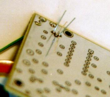
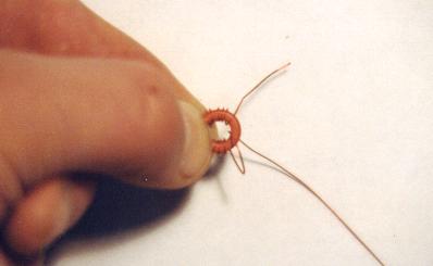
Winding the inductors L1 and L2 ... this is sometimes a feared step by kit builders, but is actually quite simple once you get the hang of it. I hold the toroid body between thumb and index finger of my left hand while threading the magnet wire through the toroid and around the ring. Remember that every time the wire passes through the center of the toroid body it counts as a turn.
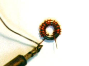
Preparing the leads of L1 and L2 ... the magnet wire is coated with a thin coat of red enamel, and in order to solder the inductor to the board you'll need to strip off this coating. The wire supplied in this kit can be stripped of its enamel coating by heating it with the tip of a hot soldering iron while applying solder to it. (See construction notes for more detail.)
Completed L1 and L2 inductors ... here you see the completed inductors after winding with 16 turns of wire, and the ends of the wires stripped.
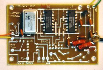
Circuit board completed with addition of L1 and L2 ... once the L1 and L2 inductors are oriented vertically to the board and soldered in at their positions, and inserting/soldering the oscillator can into the U1 position), you will have a completed FB40 circuit board! Notice the R-174 coax soldered to the circuit board "RF and GND" pad on the right ... notice especially that the ground "GND" pad and the "RF" pad is mislabeled on the board ... the coax ground should be soldered to the top pad and the center conductor should be soldered to the bottom pad. I used coax to connect the RF signal to the connector on my FB40 enclosure, but you could also use individual wires, as long as they are relatively short.
So all you have to do now to begin using your FB40 QRPp Transmitter is: (a) connect a 9V battery or any 9-14V power supply); (b) connect a 50-ohm antenna to the RF/GND pads on the right side of the board; and (c) connect a code key to the KEY/GND pads on the left side of the board.
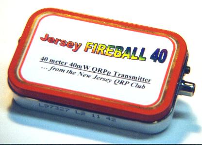
My enclosure for the FB40 ... Altoids Tin, of course! ... you cab use whatever you might have on hand in your shack to hold your brand new QRPp transmitter ... or use nothing at all!
Altoids tin makes a nice compact unit! ... just connect up a power supply (or battery), a hand key (or paddles if you provide the optional TiCK keyer from Embedded Research), and an antenna.
(Go back to Fireball 40 home page)
![]()
![]()
![]()
![]()
.jpg)