 Kit Notes

Assembly and Operating Tips
PSK-80
"Warbler"
Kit Notes
Assembly and Operating Tips
See also...
Specs
& Ordering --
Read all about the Warbler Kit and how to order
KIT
Manual
-- Download the Warbler manual -- 680KB PDF
file
> ROUND
3 CONSTRUCTION ALERT
For those
folks who purchased Warblers in the Round 3 of kittings -- only those kits
shipped/received in February have a significant
printed-circuit board error -- our pcb vendor made the boards with
the silkscreening on the wrong side!. All those who purchased
the kits have now received a new board by mail during the week of Feb 5,
including instructions for identification of the bad board and use of the
new one. In the meantime, please do not begin assembly using the bad
boards and use the replacement boards that came in the mail as a
second shipment to you. We apologize for possible confusion, but the solution
is quick and painless for most. Thanks all! .... George N2APB and
Joe N2CX.
> GETTING
FULL POWER FROM YOUR WARBLER
Some
folks have reported difficulty in getting full power out from their
Warblers. To that end the designer Dave, NN1G, has suggested changing C10
from 220 pf to 330 pf. This has helped some get 3-4 watts PEP on a 13.8 V
power supply as opposed to 2 W before the change.
Here's the word from Dave: "The NJQRP
club has already incorporated this change into the upcoming run of Warbler
kits. If you already have a Warbler, there's no reason to make this change
unless you're getting inadequate power output from the rig. If
you're already getting rated power out, this change will not yield more
output from the rig."
For what it's worth I've built two of them, a
beta and a production version and both have produced full power with the
proper power supply voltage. YMMV depending on component tolerances.
... de Joe E., N2CX
> BEING
AN SWL WHILE WAITING FOR THE WARBLER TO ARRIVE
I
can't wait till the 2nd shipment of Warblers departs NJ! I've sent
my money -- but I have the fever now!! I was so desperate after
reading all the posts from Doug, Bill, et. al., that I actually went
to Radio Shack and purchased a stereo-mini- to stereo-mini patchcord so I
could listen to PSK! The DigiPan freeware is fantastic!!! Even if
you don't have a Warbler, or any other way to transmit PSK, YOU OWE IT TO
YOURSELF TO LISTEN IN ON THE PSK QSO'S!! The software is free
(look for the links on http://www.psk31.com/
) and if you have a computer with soundcard in the shack, it is as simple
as RCVR Audio output (headphone jack) - patch to - soundcard LINE
input! ... de Alan Kaul, W6RCL, LaCanada, CA
> IMPROVE
WARBLER "IMD" WITH POT ON AUDIO INPUT
One
evening during a round table I asked several stations to check my IMD. I
was dismayed to find it was only -15 dB. This had to be fixed. I
discovered that the Windows 98 "volume" control setting changed
in rather coarse steps, not linearly. I was already down to the lowest
possible step that produced output but was still overdriving the sound
card. The cure was to break the PC board trace between J2 and the junction
of capacitors C1 and C101 and insert a 100k ohm pot. Audio from the sound
card is fed to the outside pins of the pot (from J2) and the center
(slider) connects to C1 and C101. Now with the Win98 volume control set to
mid scale I can adjust the audio drive from zero to four watts output with
DigiPan in Tune mode. I adjust the pot to the point where the rf output
just stops increasing and then back down slightly. I am happy to report
that my IMD has gone from - 15 dB to -24 dB. ... de Bill Jones, KD7S
> MORE
MOUNTING DETAILS FOR PSK-80 IN LMB-139 ENCLOSURE
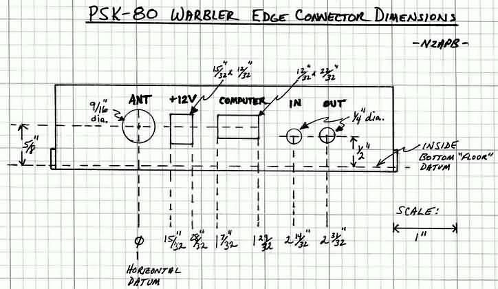
If
you use the 1/2" datum shown on the diagram
for the audio jacks to the inside bottom of the enclosure
"floor", and measure your Warbler, you'll note that a 5/16"
standoff would be needed. That is, put the 1/2" mark of a scale at
the center of one of the audio jacks and you'll see that the length of the
scale protruding below the board is the length of the standoff you would
use with the panel dimensions shown. I think I used a 1" long
4-40 screw in each corner of the board, inserted from the bottom of the
chassis and secured with a 4-40 nut to the chassis. Then I put another
4-40 nut onto each screw and ran it done tight against the first. I then
carefully angled the board connectors into the panel cutouts and slipped
the board onto the 1" screws. Finally I secured the board with
another 4-40 nut on each screw. So as it turns out, two 4-40 nuts were
about 5/16" high. ... de George N2APB
> FERRITE
CHOKE ON AUDIO CABLES CURES STRAY RF INTERFERENCE
If I
moved the cables going from the sound card to the Warbler, I found that
the output power would change slightly. I put a ferrite choke on the
cables and the problem disappeared. Note that my antenna is a roof mounted
vertical and one of the 80 meter radials passes directly over the ceiling
of my shack. It is no more than three or four feet away. And the Warbler
is sitting naked (no cabinet) on top of the desk. ... de Bill
Jones, KD7S
> CHECK OUT eHAM FOR PSK-80 BUILDER REPORTS
Post your own reviews, or see those of
others PSK-80 builders on eHAM at http://www.eham.net/reviews/detail/1137
... de Ken N9VV
> LOWERING WARBLER AUDIO OUTPUT ON COMPUTERS HAVING ONLY "MIC" INPUT
Because of the fact that I am using a Toshiba 2595CDT Laptop for PSK-31 with the "Warbler", and the laptop does not have an audio "Line" input, only a "Mic" input, the receiver audio from the Warbler was much too high for the laptop, making the entire received spectrum bright yellow. Even with the laptop's recorder mic volume turned all the way down, the screen was still mostly yellow in the received spectrum area. So, after taking a look at the schematic, I changed R23 to a much higher value. After a couple of experimental tries, I settled on 56K as a new value. With this value, the audio level to the mic input now gives the proper amount of display adjustment, from almost totally blue to pretty heavily yellow speckled. So, if your waterfall display is mostly or all yellow in the received spectrum and your volume control won't take it to the level you want, try changing R23 to a higher value. ... de Wayne
NB6M
> Q1
& Q7 PACKAGING AND MOUNTING
When the Warbler
manual was done, the FETs were packaged in the familiar TO92 style package
which has a pronounced "D" cross-section. The manual and
printed circuit board component marking was for that device. However
mid-way through the kitting we had to make a quick turnaround order for
2N7000 devices and we got them from a different distributor, what we got
was in a different case type.
So, if your Q1 and Q7 (2N7000 transistors) have the
familiar pronounced "D" cross-section packages follow the manual
and pc board markings. (This package style is the same as the 2N4401's
used at Q2, Q3, Q4 and Q9.) That is, the flat side of the transistor with
printed identification matches the flat side outline on the board and the
rounded side matches the rounded outline on the silk screening.
But if the 2N7000's you got have a flatter package with
slightly beveled edges on one side, you mount it basically the same way so
that the flatter side faces the flat side of the board marking, and the
side with the beveled edges faces the rounded edge of the board marking.
On this "alternate" style transistor package, the printing
is on the more rounded side while on the "original" style it is
on the flat side.
> R8
+ R10 VALUES CORRECTED ON PARTS LAYOUT DIAGRAM
The values of R8 (150)
and R10 (220) were inadvertently reversed on the Warbler Parts Layout
diagram in the original manual (without a rev date on the cover). The Schematic is still correct, and we have now corrected the
Parts Layout diagram. And as a bonus, the updated
PDF file on the website is now in color to help in viewing
everything!
> STANDARD
FOR RS-232 CONNECTOR ON PSK-xx BOARDS
I'm happy (so far) to
report that effective with all new PSK-series shipments, the transceiver
will use the female DB-9 connector to allow use of the ubiquitous
serial-port extender (male-to-female) cable. This is *not* merely a matter
of supplying the other connector flavor- the two genders are physically
'mirror-imaged' and they are not interchangeable on the printed-circuit
board. I'm awaiting a shipment of boards which incorporates a change
in this regard.
Along the way, I'd heard from several people who threw
away the connector I provided and specified and installed one which
matched the picture in QST. Bad move- that picture made a QST
deadline with only hours to spare, and once I actually applied power,
quickly discovered that there was little Transmit Joy!
Anyhow, there's nothing to 'vote' on. Both
the PSK-series and the Warbler will now use the female board-mounted
connector. If you've already got a PSK-20 and want to switch back and
forth to a Warbler or a PSK-40 <g>, a 'gender-bender' plug
(straight- not null modem) is available from Radio Shack, Jameco,
etc...
... de Dave, NN1G
> FINDING
THE LMB-139 ENCLOSURE
In the Tech Manual, and during my PSK
talk at Pacificon, we showed a nice and conveniently-sized Warbler
enclosure called the LMB-139. There's really nothing special about this
aluminum clamshell design from LMB -- one could use just about any handy
enclosure in the junk box (or even make a NJ Homebrew PCB enclosure!!) --
but it just turned out that the LMB-139 fits snugly around the PSK-80
Warbler circuit board. I've used these enclosures for several years
for my QRP projects in the shack, and you can see some of the results at http://www.njqrp.club/mbrproj/enclosures.html
Tom Jennings, KV2X tells us that you can order the LMB
enclosure directly from LMB (http://www.lmbheeger.com/products.htm).
And NN1G reminds us that many other enclosures will work, so check out the
Jameco (http://www.jameco.com), Mouser
(http://www.mouser.com) and Digi-Key
(http://www.digi-key.com)
sites! ... de George, N2APB
> RUNNING
THE PSK-xx BOARDS WITH A MAC?
A number of QRPers
have written to ask if there's a software program for the Macintosh
equivalent to Digipan on the PC that controls the PSK-xx boards. Well
there is! Check out Multimode at http://www.kender.es/~edu/psk31.html
There is also a neat new one for Linux by a German, but the link eludes me
at the moment. ... de Skip KH6TY/4
> WD9EYB
RUNNING A WARBLER GROUP BUILDING PROJECT
I have slapped on
some of the things I have said about a group building project of PSK-80's
for West Central Indiana and East Central Illinois at http://butler.qrp.com/~wd9eyb/psk80/rantings.html
... Jim, WD9EYB
> KD7S
STARTS "WESTERN WARBLIERS" NET - SUNDAYS 7PM PST
I've
always wanted to coin a new word or phrase, so here goes:
Warblier (warbel-ear), n 1. One who operates PSK-31, esp.
with a NJ QRP Club PSK-80 Warbler transceiver. 2. Anyone running
PSK-31 (BPSK or QPSK) with any kind of transceiver, QRP or QRO.
George Heron sold a hundred Warbler kits at Pacificon
[and another 100 via mail]. I would guess that 50% of those kits
went to west coast QRPers who live within a couple hundred miles of the
bay area. If you're one of those, how about joining Doug (KI6DS),
Dave (AB5PC) and myself (KD7S) in a round table chat on 80 meters.
Set up DigiPan on 80 meters at 3582 kHz, BPSK, LSB and
a 1,500 Hz tone. Activate AFC, NET and SNAP. If you chose to use
Squelch, set the threshold fairly low (no more than 2-3 notches from the
bottom).
I'd like to suggest we create a "Western Warbliers"
round table QSO party on Sunday evenings beginning at 7:00 p.m. PST.
No net control, no formal check-ins, just a round table discussion using
PSK-31 running 5 watts or less from any rig (but especially the Warbler).
Who's in?
... de Bill Jones - KD7S, Sanger, California
> MONITOR
PSK31 ACTIVITY ON PSK-xx BOARDS WITHOUT A COMPUTER
I
monitor the receive audio output with a small amplified speaker and can
tell if there is activity on the frequency without using the computer.
... Dave Epps, AB5PC, Fresno, CA
> EASY
WAY TO MOUNT CRYSTALS ELEVATED FROM PCB
To
allow for spacing between the crystals and the board I cut a strip of
heavy paper (or whatever) the thickness of the crystal. I then cut a slot
in the center of this strip and slide it between the crystal and the
board. Solder and pull out the strip.
... Dave Epps, AB5PC, Fresno, CA
> ALIGN
YOUR WARBLER WITHOUT W1AW
I've
heard talk about how some PSK-80 Warblers that don't hear well or have low
power output. One possible explanation is that they are not aligned
properly. The manual touches briefly on alignment usingW1AW as
a frequency marker. Unfortunately, some of us on the west coast
can't hear W1AW on 80 meters. I used my own transceiver to align my
Warbler. Here's how ...
1. In DigiPan, click on the "Configure" menu.
2. Click on "Band."
3. Click the "Activate" button for 80m under
"Band."
4. Under Spectrum Start" type 3582.
5. Under "Spectrum Options" click on LSB.
6. Click "Okay."
7. Fire up your Yaecomwood, set it up for QRP and CW
operation.
8. Attach a dummy load to the Yaecomwood.
9. Set the dial to exactly 3581.00 kHz.
10. Key the Yaecomwood. You should be able to see its
signal in the DigiPan waterfall.
11. Adjust trimmer C3 on the Warbler board until the signal
is directly under 3581 on the DigiPan display. Your Warbler will now
be calibrated to the accuracy of the frequency display on the big rig.
Click the waterfall at about 3580.5 kHz. From the
DigiPan menu, click "Mode" and "Tune. With a 13.8
volt power supply you should see about3 or 4 watts output. Your
transmitter output power should drop off below 3580 and above3581
kHz. That's normal. On my Warbler, the "sweet
spot" is right at 3580.5 kHz and is fairly flat 400 Hz either side.
... de Bill KD7S
> HOW
DO YOU HOOK IT UP??
One of the questions that I had about my warbler once I
got it built was how to hook it up to the computer and the outside world.
Bill Jones, KD7S and Paul Maciel, AK1P have been my PSK gurus. You
will need the following to connect and get on the air:
1. Power cord (NJQRP supplies the cord and the plug, NICE touch)
2. BNC cord to connect to your antenna. If your antenna coax
ends in a PL259, then you will need an adapter to connect to the BNC
connector on the Warbler.
3. DB9 Male to DB9 Female cable to connect between the Warbler and
the serial port on your computer.
4. Two shielded audio cables with stereo 1/8" plugs on both
ends. One connects to the Mike input of your sound card and the
audio output of the Warbler, and the other connects to the audio ouput of
the computer and the audio input of the warbler. (Hope I got that
right, grin). 5. Digipan or similar software installed on your
computer. (Available from a link on Dave Benson's Small Wonder Labs
page, www.smallwonderlabs.com
look under PSK31)
The antenna that I am using is a Skelton Cone up about
30 feet at the apex and 6 to 10 feet at the end of the radiators. A
skelton cone is basically a double dipole. Think of having 2
radiators on each side of the center insulator spread apart, instead of
just 1. It is fed with ladder line and tuned with a tuner.
Works on all bands. The legs are 51 feet long, and the feedline is about
50 feet.
With my setup, I am able to work both close in and dx
stations, having solid copy on the locals, and being able to work NW7DX
from Washington and KI0RO from Colorado. Hope this helps. ...
de Doug KI6DS
> WHAT
KIND OF DISTANCE ARE YOU 80m PSK OPS GETTING?
I'm using a low dipole
at my Connecticut QTH - it's up only 12-13' at the center. Copy is solid
out to 200+ miles, although it varies some with conditions. My 2-way with
Joe, N2CX, near Philly was about 80% both ways with our Warblers, and I've
had a rock-solid QSO with a VE2 in Sherbrooke-about 250 miles. Best
DX to date has been the Atlanta area but it was a struggle.
Distances seem comparable to what you'd work using CW.
Just since I first put the Warbler prototype on the air
last spring, I've watched the PSK31 activity growing on 80M. Here in the
Northeast, you'll usually see one or more traces on the display at night,
especially during W1AW's quiet period (9-10 PM Eastern). I've seen as many
as 4 simultaneous traces in the Warbler's 1 Khz passband. That
doesn't even begin to fill that slice of spectrum with PSK31! We've got a
unique opportunity here to "make it happen".
Don't let the fact that it's 80M, as opposed to a 'DX'
band, deter you in the slightest. Many of us are running short (or low)
antennas and still getting out. Joe Everhart's 'Squirt' antenna is
half-sized and gets out quite well- look for it in the next issue of the
NJ QRP club's 'Homebrewer' journal. From the sound of Doug's
recent post, none of the antennas in their wonderful 3-way QSO was a
'killer' skywire.
This is the season to begin thinking about the low
bands, and enthusiasm for 80M yields creativity in the antenna area. This
is something we all enjoy hearing about, whether we're WarbleHeads or not,
and this enthusiasm gets us off our computers (maybe) and *on the air*.
... 73- Dave, NN1G
> CUTTING
THE REAR PANEL OF YOUR ENCLOSURE
Here's a convenient diagram
showing hole dimensions for the "rear panel" of any
enclosure you might happen to put the Warbler into. As illustrated, the
enclosure happens to be of the LMB-139 aluminum clamshell, but the
dimensions are really only specific to the edge connectors of the PSK-80
board. Hence, you can use this diagram as a template (when
reproduced at actual size) for making the cutouts in your own panel, or
just use the dimensions to map out the holes needed on any panel you might
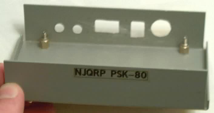
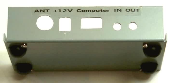
want to use. Also shown are a couple photos of the LMB-139 enclosure
used in the manual, but shown without the board in place this time.
These shots illustrate two things: (1) the board
standoff scheme I used for this enclosure, and (2) the
imperfection of my cutouts ... but they are "good
enough", as N2CX would say! :-) ... de George N2APB
> MAKING
A PANEL TEMPLATE & USING NUT/BOLT STANDOFFS
Cut
a piece of heavy paper (file folder stock) to the exact dimensions of the
front of your enclosure. Then using an inexpensive (plastic, $1.00)
calipers, or even a ruler, measure the positions of your controls, etc.
with reference to some landmark, such as the bottom right corner of the PC
board. Lay these dimensions out on your paper replica and make the
holes with a paper punch. Then test it out, moving the holes as
necessary. When everything is right, cut a new replica and transfer
your accurate dimensions to it to make a template. Then proceed as
you would with a "real" template.
With regard to the using nuts as a standoff.
You can make this adjustable if you run a screw (4-40 size, for example)
up through the bottom of the enclosure and secure it with a nut (and
possibly a lockwasher). Then thread another nut down the screw to
achieve the desired height. Leave some space between the nuts, and
you can make very fine adjustments of the standoff height. Then
mount the board on the screws and secure it with a third nut.
... de Richard Meiss, WB9LPU
> 7.5V Zener Diodes are
1N5236B
Bruce Prior, N7RR pointed out a helpful
hint for the Parts List in the manual ... D1 and D2 part numbers are
1N5236B. This should help distinguish them from the other diodes in
the package. Thanks Bruce!
> T2 CONSTRUCTION & LAYOUT CLARIFICATION
Thanks to the early-on assembly of the
production board by Dave Epps AB5PC, and to the artistry of designer Dave Benson
NN1G, we have some clarifying diagrams for the construction and installation of
transformer T2. Click HERE for picture details.
> FIRST
WARBLER-WARBLER-WARBLER QSO: KD7S-AB5PC-KI6DS
Although Chuck Adams, K7QO had the first
production-version Warbler contact last week right after Pacificon, Bill
Jones KD7S and Dave Epps AB5PC had the first production-version
Warbler-to-Warbler 80m PSK31 contact on October 28. And to top it
off, Doug Hendricks, KI6DS hopped in for the first Warbler round table QSO
with Bill and Dave! Read more about it HERE.
> UPDATED MANUAL
+ SCHEMATIC + LAYOUT AVAILABLE
ONLINE
A small number of manual and parts
list corrections (listed in the next section) have been made to the Warbler
Technical Manual to create a "rev B" of the manual. If you'd
like to see or possibly print this revised manual, you may download the Warbler
Technical Manual - Rev B. You can also download the Schematic
and Parts Layout diagram. (Note: You'll need to have Adobe
Acrobat on your computer in order to read this 330K PDF file.)
> ERRATA and CLARIFICATIONS
1) Heatsinks ... The heatsinks provided in the
kits sold at Pacificon were the wrong size. Contact N2APB by email (n2apb@amsat.org)
to receive
the correct heatsinks. (All kits received by mail already contain the correct
heatsink.)
2) Magnet Wire ... The kits supplied at
Pacificon didn't have enough magnet wire (used in creating T2 and L2). A
6" length of magnet wire will also be sent in the package containing the
correct heatsinks.
3) Stranded Wire ... Stranded multi-color
telephone wire is supplied in the kit, instead of the specified solid conductor
wire. The stranded wire will work just fine.
4) T1 winding clarification (Step 7 on page 7) ....
"T1 is wound using three 4-inch lengths of wire (leave insulation on)
removed from the 4-conductor cable supplied. Four (4)
turns of these three wires are wound flat on a dark grey core, with
no wire crossing over its neighbors."
5) T2 winding clarification (Step 8 on page 7) ... "T2
has a primary winding and separate secondary winding. The secondary should first
be wound using 8 turns of magnet wire distributed uniformly around the
circumference of a dark grey core. ... The primary is wound next using
two 4-inch lengths of distinctly-colored wire from the 4-conductor cable. The
two wires are 'bifilar wound', wound together for 4 turns over the
magnet wire secondary already on the core. ... The magnet wire winding
connects to the output harmonic filter and should be installed in the rightmost
pair of T2 holes."
6) Surface
Mount IC orientation (Step 2 on page 5) ... "When the lettering on the
IC reads 'upright', the chip is in the same orientation as shown in
the Board Layout diagram. Then, pin 1 is in the lower left corner of the
device."
7) Final Transistors ... 2SC2166 transistors
are supplied for Q5 & Q6 in the kits, instead of the 2SC2078 devices noted
on the
schematic. For our purposes, they are equivalent.
8) Theory of
Op "typo" ... the last paragraph (on page 4) in the theory of op
section should reference Q8 as being turned on in the T-R switching.
9) Parts
List "typos" ...
- the 2N4401 transistor is used for Q2, Q3, Q4 and Q9
- the 2N7000 transistor is used for Q1 and Q7.
- C11 & C12 may be blue or yellow
- W3 should be 20"
> REVIEWERS
Thanks go to Chuck Adams (K7QO), Dave Meacham (W6EMD), and Dave Epps (AB5PC) for their careful
attention in assembling the kits and noting clarifications for everyone.
![]()
![]()
![]()