![]()
QuickieLab v1
PCB Modifications
![]()
Several "cuts & adds" need to be made to the rev 1.0 version of the QuickieLab PC board for it to work as designed. I had some problems when flowing the ground plane on the bottom side of the board during layout, and some errors went undetected when updating the prototype layout to the final production layout.
Thanks to those diligent individuals who helped find the errors: Lee Mairs KM4YY, Tom Feeney W8KOX, Nancy Feeney NJ8B, and Dov Rabinowitz AD0V.
I apologize for the inconvenience this causes and I'll be adjusting my process of laying out boards such that these types of errors don't happen again. (The good news is that once these changes are made, the QuickieLab production board works like a champ, just like the numerous prototype boards we had in the beta trial!)
73, George N2APB n2apb@amsat.org
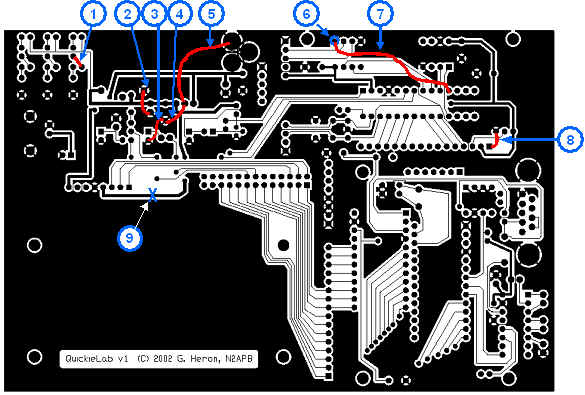
PCB MODS:
1. Add jumper as shown.
2. Add jumper as shown.
3. Add jumper as shown.
4. Add jumper as shown.
5. Add jumper as shown.
6. Cut both thin connections from pad to the ground plan.
7. Add jumper as shown.
8. Add jumper as shown.
9. Cut trace that supplies 5V to DDS Daughtercard connector.
Back to QuickieLab "Notes" page
![]()
![]()
![]()