![]()
QuickieLab v1
PCB Layout
![]()

*
NOTE:
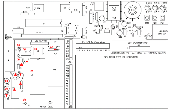
I provided board traces for those who wish to use a cheaper solution than the
BS2 (BASIC Stamp 2) from Parallax.com. For about half the price of a BS2,
Peter Anderson (www.phanderson.com) provides a "Homebrew Stamp" chip
set that performs identically to the BS2. The components noted with a red
asterisk in the Layout diagram above are those associated with the
Homebrew Stamp. You cannot use both solutions at the same time ...
so follow the simple guidelines as follows ...
If you use the Peter Anderson "Homebrew Stamp" chip set, these parts should be populated on the board: U1, U2, U3, C1, C2, C3, C4, C5, C6, C7, C8, R1, R2, R14, D1 and Y1. It is an intuitively obvious operation to populate components according to the schematic supplied in the Homebrew Stamp instructions.
If you use the BS2 controller, leave the red asterisk positions empty on the PC board and use the BS2 chip in the U4 position.
Back to QuickieLab "Construction Notes" page
![]()