QuickieLab AppNote #2
the VXO-Mate
![]()
QuickieLab AppNote #2
the
VXO-Mate
![]()
Control a VXO and display its frequency with an LCD and Morse annunciation
Joe Everhart, N2CX email: n2cx@voicenet.com
This application note describes how to construct a voltage-tuned crystal oscillator using the QuickieLab. This test gadget monitors the tuning voltage and oscillator output frequency of a VXO (variable crystal oscillator) and displays them both to an LCD display. Building on the QuickieLab AppNote #1, it offers both visual and audible “display” options and provides a selectable audible Morse output for both the voltage and frequency readouts.
VXO-Mate
The VXO-Mate is a project that was really inspired by a design competition at the 2002 NorCal QRPacificon event. Doug Hendricks and some of his left coast henchmen once again came up with a really different event. Providing a kit of parts to be used at a small charge they specified a voltage-tuned VXO to be built ahead of time and tested competitively during one of the evening sessions. Using a common set of crystals and varicaps the competitors were to devise circuits that provided the maximum stable tuning range.
This piqued my curiosity not only in entering the competition, but also by adding some of my own creativity to build a companion piece of test equipment to accompany the VXO. Building on the NJQRP Quickielab, this was actually a rather simple task. Since it is an adjunct to the VXO and since Dave Benson came up with a catchy new name for his latest rig, the test gadget was dubbed the VXO-Mate!
The VXO for the contest is a voltage-tuned crystal oscillator. This test gadget monitors the VXO tuning voltage and the oscillator output frequency and displays them both. Building on the QuickieLab projects already described, it offers both visual and audible “display” options. The standard display is a LCD device. However there is also a selectable audible Morse output for both the voltage and frequency readouts. Since it is an adjunct to the VXO and since Dave Benson came up with a catchy new name for his latest rig, the test gadget was dubbed the VXO-Mate!
Configuration
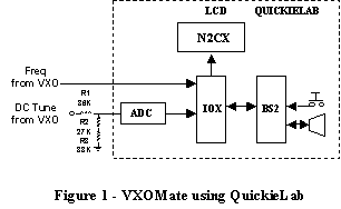
Figure 1 shows the exceedingly simple conceptual block diagram. The heart (well, maybe the brains) of the QuickieLab is a Parallax BASIC Stamp 2 chip. It acts as a controller to run the overall program that coordinates what is going on. Most of the “grunt work” though is done by a peripheral chip, the IOX or Input-Output Expander. As described in Ref 3 this device, running under control of the BS2 performs the auxiliary functions of frequency counting, Analog to digital voltage conversion and running the LCD display. Without the IOX the BS2 would be far too busy minding the Quickielab auxiliary chips to even consider doing anything else. But with the IOX it loafs along and can do its coordination and number-crunching functions.

99% of what’s needed to make the project is already on the QuickieLab board. All of the chip functions, connections, LCD screen and the loudspeaker are self-contained. Literally the only components added are several resistors needed to set the input voltage range for the Analog to Digital Converter. As shown in Figure 1 they are needed to divide the anticipated 8-volt tuning voltage down to the maximum 5-volt input level that the ADC expects. Precision resistors would be best but 5% resistors of the values shown are adequate. Alternatively you could get the same ratio with a 39k resistor for R1, a 56k for R2 and a 10K pot for R3. Best calibration would be done by setting the input to 8 volts and adjusting the pot until the VXO-Mate read 5 volts. Alternatively you could simply use the same input voltage but adjust R3 for a DVM reading of 5 volts at the ADC input.
Software
A complete program listing for the
VXO-Mate can be
viewed. (If you wish to save this to your computer, right click on this
link and use "Save As ..." to select the destination on your local
hard drive. Then change the extension from txt to bs2 and your Stamp
editor will properly recognize the software file.)
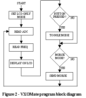
A simple flow chart for the VXO-Mate is provided in Figure 2. The VXO voltage and frequency are monitored and displayed on the LCD screen each time through. After the LCD screen one of the built-in QuickieLab pushbuttons is checked. If it is depressed, a mode change is made. In this mode, the same voltage and current readings are annunciated in Morse code on the QuickieLab loudspeaker. The cycle starts over again with new readings and once more the pushbutton is checked after the LCD display. If it is depressed the mode toggles back to the LCD only mode. If not, the program remains in the “sight and sound” mode.

The voltage display on the LCD shows three digits with a decimal point and the units of “V” for volts. The frequency display has a total of 8 digits, tens and units of Megahertz and six more to go down to one hertz resolution. Since the display has only 16 digits, the frequency unit is abbreviated from “HZ” to “H.”
The Morse output mirrors the visual display. The volt output has three digits with an “R” for the decimal point and a trailing “V” to identify the voltage “display.” Frequency is always 8 digits. The first two (Tens and Units of Hz) are zeroes if the measured frequency is below 10 MHz. Again an “R” is sent as a separator after the Megahertz digit then there are six more digits. Since the frequency annunciation has so many digits the “H” is not sent. Also, since the frequency string is so long, “0” digits are sent as “-“ much as contesters do. This minimizes sending time without sacrificing intelligibility.
Figure 3 shows a typical LCD display of the VXO-Mate data.

Possible Improvements
The VXO-Mate was brought to life as a quick demonstration of the capabilities of the QuickieLab. As such only minimal additions were made to the basic circuit. As with any project it can be improved at the sacrifice of added complexity.
The first such improvement is to add more accuracy and precision to the ADC. First off the internal ADC uses the QuickieLab’s 5 volt power supply for its reference. Its accuracy can thus be no better than the 5% accuracy of the 7805 regulator. One way to improve accuracy would be to add a precision reference voltage. Yet another would be to retain use of the current 5-volt reference but to augment the operating software with a user-selectable calibration routine. The latter method has the beauty of needing no hardware changes.
The current 8-bit ADC has only 8–bit resolution. So it is inherently limited to no better than about 0.4% resolution. This means that the granularity of readings is about 0.03 volts (8V/256).
10 and even 12-bit serial-interface ADCs are available quite cheaply and could be interfaced directly to the BS2 chip. This does tie up three additional I/O pins however. A future Quickie will likely detail how to do this.
The frequency counter is similarly not a super-accurate device. Its ultimate accuracy is limited to that of the IOX clock oscillator. There is, as with all devices, a tolerance on the IOX resonator accuracy and no trimmer is provided to set it “dead on.” This may or may not be easy to do. However it would be possible to improve the accuracy of frequency measurements by, once again, adding a user-selectable calibration routine in the BS2 program. This could adjust out the static tolerance error inherent in the resonator and would likely be good enough for room temperature applications. The dedicated accuracy freak could remove the 50 MHz resonator and replace it with a calibrated 50 MHz oscillator. [Note: A crystal is now being supplied instead of the resonator in I/O Expander IC purchases.]
A program enhancement that was originally intended but not implemented due to lack of time is to automate VXO measurement even more. The VXO-Mate can be simply modified to provide a DC control voltage output. With suitable program changes the unit can automatically sweep the entire tuning range while monitoring the output frequency. Using this info it would be a snap to calculate the min-max tuning range and other items such as tuning linearity and tuning sensitivity in terms of kHz/volt.
Even without enhancements however the VXO-Mate is a real-world example of how simply the QuickieLab can be put to use. It is not meant to be an aerospace lab quality instrument but instead a handy device that can be quickly adapted for special needs much the same as you would a circuit breadboard.
![]()