![]()

The Poqet PC is a great little computer, with the possible exception of the display. The Plus model, however, is definitely a much better computer. It’s a lot faster (uses a NEC V30 chip) and the backlit display is easy on the eyes.
When I heard from Jerry at Disks ‘n Data that he had a bunch of plusses without the serial adaptors, I decided to see if I could either locate the plugs that connect to those two rear connectors. After talking to AMP, Fujitsu, and several surplus dealers, I still haven’t come up with a part number or even a name for the connector type.
This is a fairly straightforward job. It does, however, involve soldering very small joints in a confined space. A magnifying lamp is a big help. It’s also nice because there are no physical modifications needed for the computer, and it can be easily reversed. At this point, I have to make a couple of disclaimers here.
First, the modification as described was performed by me and it works. I can’t, however, take responsibility for anyone else’s attempt to perform it. I went into this prepared for the possibility that I was committing "computercide". If you feel uncomfortable with it, don’t try it. Second, I am not now nor have I ever been a member of Disks ‘n Data. Jerry’s just a great guy to do business with.
Here’s a list of what you’ll need:
Parts:
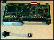
(see Fig. 1)One DB-9 male connector. (I used a spare connector from an I/O card. I even had the ribbon cable connected)
Mounting bracket for DB-9. (Here again I used surplus parts from an old PC card).
Bracket Spacers. I used a couple of threaded motherboard standoffs.Tools:
Jeweler’s screwdriver set.
Small wire cutters.
Soldering iron w/small tip.
Tin snips.
File.Disassembly:
Before starting, remove the battery pack, memory cards and backup battery from the unit. The battery is located in a small compartment on the bottom. Remove the single screw and the cover, and pull the connector from the computer. All that’s necessary after that is to remove the rear section/display module. (See fig 1 and 2, below)
Open the computer up and set the display vertical. Remove the two screws from the bottom rear corners of the case. Using a small screwdriver gently pry at the right corner of the display subassembly. Continue gently prying in the gap between the top of the keyboard and the display subassembly. (Between the function keys and their labels)
The left hinge can be eased out in the same manner, but it may be tight. There’s a metal friction hinge on this side, so make note of the metal tab and be sure to line it up correctly on reassembly.
Carefully pull the assembly up and rotate to the rear. There are two cables on the right side connecting to the mainboard. Pull the connector with the wire pair. The other cable is a flat plastic strip with conductors on one side. Release the flat cable by pushing the tabs on either side towards the cable. Handle this cable gently. The cover/display can be removed.
It’s not necessary to remove the keyboard, but here’s how: Remove the last 4 screws from the bottom of the case. Push the keyboard slightly to the rear and gently pry on the right and left sides. Remove it carefully and rotate it towards you. There is another of the flat plastic cables connecting it to the board. Release the cable and set the keyboard aside.
The final item to remove is a plastic piece that is over the I/O connectors. Just remove the 2 screws holding it in and set it aside. Now you’re ready to set up the DB-9.
Mounting Bracket and DB-9:
For a mounting bracket I used an end plate from an old video card. It was already punched out for the connector. Using my tin snips, I trimmed the bottom tab off and then cut it to cover both of the mounting holes. (About 3.75") Try to align the DB-9 centered on the existing connector. Drill 2 holes to mate up with the screw holes on the back of the computer. Eventually, I plan on making a less obtrusive mounting bracket out of plastic.
Remove the mounting spacers from the DB-9 and trim the ribbon cable to about 1.5 – 2" long. Separate the individual wires in the ribbon cable, strip about 1/16" from the ends and tin them.
Installing The Mod:
Look closely at the right rear corner of the computer. The connectors are soldered to the top and bottom of the board. We’ll be using the large connector and the top connections only. Note that pin 1 is marked on the mainboard, and simply count to the right.
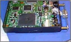
Now the tricky part. The connections on the mainboard are very close together. Take a Q-Tip and some alcohol and clean the connections. I ground down a soldering tip to a very fine point. (See Fig. 3)
Using an appropriate amount of heat, tin each connection lightly. I found it easiest to touch the iron to the solder and then touch the connection. Keep the iron clean and be extremely careful to avoid any solder bridges. If necessary, use a solder sucker or braid to remove excess. Do not keep heat on the connections for too long. I found a higher heat allowed me to get in and out quicker.
Take the DB-9 and slide the wires through the case between the top of the large connector and the case. There’s plenty of room to get them through. Begin soldering the wires o the connections using the same technique you used for tinning. I also used a pair on long nose pliers to hold the wire in position. Then, touch the solder and immediately touch the wire against the connection. Hold it for a few seconds, and that’ll do it. (Watch out for them solder bridges) The table below has the pinouts for the computer, DB-25 and DB9 connectors:
Poqet Plus
DB-25
DB-9
Designation
2
2
3
TXD
3
4
7
RTS
4
20
4
DTR
5
7
5
GND
6
3
2
RXD
7
5
8
CTS
8
6
6
DSR
9
8
1
DCD
10
22
9
RING IND.
Reassembly and Testing:
Carefully inspect the solder connections. Thread in the standoffs on the back. (NOTE: the hole on the corner is shallow. You may have to shorten the stud to run it all the way in. DO NOT force it – you could pull out the brass insert!)
Mount the DB-9 to the bracket, and mount it to the standoffs. Be sure to push any excess wire into the computer. Replace the small plastic piece using the 2 screws. You may have to move the wires around a bit to get it seated properly.
Reconnect the plastic flat cable by inserting it into its connector and pushing the side tabs back against the housing. This can be difficult, so be careful and make sure the cable is firmly seated before locking it in. Insert the other connector into its socket.
The final step is to line up and install the subassembly. Make sure the metal tab and led lens are lined up and snap everything back together. You may need that small screwdriver to help it along. Finally, replace the last 2 screws and admire your work.
All that’s left is to put the backup battery back, insert the memory cards and battery pack and fire it up.
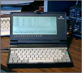
I tested the port using the PK88 packet program. After a couple of false starts and resets, I connected to my PK-88 on Com1 at 9600. From there, it worked like a charm. I logged on to the local DX cluster, checked DX and logged off. You could also use any dumb terminal program and connect to either your TNC or an external modem. (Fig. 4)
There it is. Good luck.
73 de Bob/KB2SGM
kb2sgm@home.comFigure 1:
(from bottom) DB-9 with ribbon cable. Modified PC card mounting bracket. PC Plus mainboard in case.
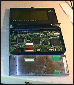
Figure 2: Basic Subassemblies (from bottom). Keyboard. Mainboard/Bottom Case. Display/Top Cover.
Figure 3: Connector in place and ready to reassemble.
Figure 4: Poqet Plus connected to the NJDXA Cluster (W2JT). The TNC is connected to Com1, via the newly installed DB-9.
![]()
![]()
![]()
![]()