![]()

![]()
The NJ-QRP MicroBeacon
The Design Phase
by: George Heron N2APB, Joe Everhart N2CX and Bob Applegate K2UD
INTRODUCTION
In part 1 of this project series (Spring 1998 QRPp) we presented the Concept and Requirements phases for the New Jersey QRP Club "MicroBeacon." This project is a collaborative effort being done by our club membership to specify, design and construct a low-cost, flexible and completely open keyer/beacon by following the industry-standard techniques of phased development.
By saying that this is an "open project" we refer to the availability and tutorial nature of the software source code used to control the MicroBeacon … with this software in-hand nearly anyone can easily get into the fascinating world of microcontroller programming.
We'll be describing the Design phase in this article installment by building off the requirements specified last time to detail the actual hardware and software design, parts selection and tradeoff considerations made in getting to our first working prototype of the MicroBeacon. We'll wrap up the project series in the following issue of QRPp by presenting full schematic and software details, prototype construction and review of MicroBeacon field usage.
THE BIG PICTURE
The major components of the design, as specified in the project requirements, consist of: (1) the Microcontroller, (2) the User Interface, and (3) the Attenuator. Refer to the system diagram in Figure 1.
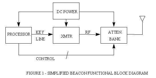
Basically the Microcontroller (with paddle input) keys the transmitter, whose RF output is coupled through a programmable attenuator controlled again by the Microcontroller. All of this is under software control: keyer speed/memories/options, along with power control of the transmitter being used.
THE MICROCONTROLLER
Selection of the appropriate microcontroller for this project was a tough and debatable topic. This decision caused the most discussion among our membership on the listerv … everybody has a favorite controller and desire for one vendor or another. Ultimately we settled on the Microchip PIC family mainly because of its intrinsic ease of programming, for its relative low cost, and for its popularity in many discussion groups and other projects. This educational benefit is of great importance in the project requirements.
Referring to "Figure 1: Detailed Block Diagram", our microcontroller needs to control many devices and serve a variety of demanding functions. We need to have 14-or-so output control lines, be able to read 6 input lines, communicate serially to a host PC, generate a side tone and determine a potentiometer setting through an A/D converter. The microcontroller must be easy to program, reprogram, and reprogram again during the development cycle, for us the design team as well as others who may wish to modify the software later on for their own use, per the source code we provide as a starting point.
We chose the PIC16C74A microcontroller because of its high I/O capacity, its built-in A/D converter port, its built-in serial communications port, it's pulse width modulation (PWM) port capability, and for its simplicity of programming. The microcontroller costs about 10 bucks in single quantities, but for all you get (and for all the parts we don't need because of the PIC's integrated functionality) the price is rather attractive. The '16C74A is an 8-bit CMOS RISC, fully static microcontroller in a 40-pin plastic DIP package containing 4KB of program memory and 192 bytes of RAM for keyer and beacon memories. You can see the full spec sheet (288 pages worth!) at the Microchip website: http://www.microchip.com.
Programming the PIC16C74A is also very straightforward. All one needs to do is build/buy a simple programmer (we use the EPIC programming board from Jameco, priced at about $75) and connect it up to the serial port of your PC. Using public domain software (i.e., free assembler and downloader!), you can quickly program your own PIC in almost a blink of an eye. Further, a version of the PIC comes with a quartz window in the package allowing for erasure of the program by a UV lamp so you can download your new program to the device and use it again and again. New feature, personalized beacon messages, bug fixes, speed defaults, and many other software customizations become easy as pie to do.
THE USER INTERFACE
Perhaps the most important and visible aspect of a project is the "user interface", or the controls and indicators used by the user while operating the MicroBeacon. We detailed the functional requirements pretty carefully in the last installment, and now we'll take you through just how we realized them all in order to provide a usable unit.
The main way that the MicroBeacon has of communicating with the user is by means of a simple, inexpensive 1-line-by-16-character LCD display. The microcontroller is able to display status (e.g., what memory is playing), prompt the user for input (e.g., "Power level?:") and to display mode, keying speed, and more. We opted for use of the LCD over some less expensive display/feedback alternatives (like LEDs or audible Morse code) because of its inherent greater flexibility. Rock bottom project cost wasn't a high priority requirement, so we selected a flexible display device that was very user friendly.
We decided to use a keypad on the front panel to provide the user with a way to input various parameters and to easily navigate through a myriad of configuration options presented in the MicroBeacon. We considered using a bunch of pushbuttons as in some other popular memory keyers but we felt that a miniature keypad (like those used in tone pads on HT mics) would be more elegant and flexible in the longer run.
Other user interface devices include a pot for conventional speed adjust (much better than entering digits via the keypad!), and a sidetone generated by a digital pulse train off one of the microcontroller's PWM outputs (with a simple LPF to smooth it out).
ATTENUATOR
If the processor selection was the most debatable topic in the design of the MicroBeacon, then the attenuator was certainly the most challenging and most interesting problem to solve.
The current practice in beacon transmitters seems to be the use of no more than a watt as the maximum power level. This is in keeping with the spirit of QRP in using the minimum power necessary. In addition, since the beacons are often used on the more popular amateur bands, it is important that they not generate excessive QRM. With good antennas 40 meter beacons have been received over distances of several hundred miles during daylight and several times that distance at night, down to low milliwatt outputs.
Beacons operated recently by AA4XX and WA3NNA have used power levels which decrease in steps of 10 dB. On HF the minimum easily discernible difference in power levels is about 3 dB, and since one S-unit is 6 dB, it is recommended that the increments (decrements) be no smaller than 6 dB.
Potential Implementation Methods
Given the requirement of interfacing to an existing transmitter, we explored several methods of power control.
1. Switched Attenuator -- Benefits here are that the transmitter need not be modified in any way and the conceptual simplicity is elegant. Disadvantages include: (a) the need to dissipate nearly the full output power of the transmitter under some circumstances; (b) the possibility of needing a physically large device, depending on the power dissipation, the type of attenuators used and the means used for switching the attenuator sections; and (c) a potentially high power dissipation for the attenuator switches. Probably the best type of attenuator to use is a "pi" type of attenuator composed of carbon composition or carbon film resistors. 50 ohm attenuator pads are very easy to design and will give reasonably accurate results using inexpensive 5% resistors.
The two easiest types of switches are PIN diodes and relays. PIN diodes seem attractive at first glance, but tend to be fairly complicated in a multi-attenuator configuration. Their microsecond switching speed is not needed in this application. Power dissipation can be on rather high, on the order of 100 mW or more switch. In addition, isolation may be only 30 to 40 dB, requiring special techniques if high-value attenuators are used.
Relays may be a better choice when considering a switched attenuator design. They are relatively small. A candidate is the Omron G6H-2-DC-12, available from Digikey for $4.22 each. It is a dpdt relay that is only 5x14x9mm and has a low operating power requirement of only about 12 ma (1028 ohm coil resistance at 12 volts).
The simplest way of arranging the attenuators to be switched is to put them in cascade, and arrange the dpdt relay to either bypass them individually when powered off, or put the selected one in line when its associated relay is energized. This is identical to the way that manually switched lab type attenuators are built.
A means of reducing operating current for the attenuator even further is to use a latching type relay. This type has two coils, one to toggle back and forth between the two relay states when pulsed briefly. The disadvantage is additional circuit complexity, but that is minimal. A candidate latching relay is the Omron G6HK-2-DC-12 which has the same dimensions as the non-latching type mentioned above and is also available from Digikey for $5.22.
2. Adjusting Supply Voltage to Set Output Level
RF output power from a class-C amplifier is approximately proportional to the square of the DC supply voltage. Thus an output stage that supplies 5 watts at 12 v DC will produce about 2 watts at 7.6 volts and 1 watt at 5.37 volts.
For a 5 watt transmitter, pretty good output control can be maintained down to about 100 mW. DC control can be easily accomplished by means of an integrated circuit linear voltage regulator and switched resistors to set the voltage. And power levels can be accurately calibrated for a given transmitter using switched potentiometers and fairly good stability and repeatability are expected.
Another Method: Ingenuity Strikes!
The approach we ultimately settled on for our first prototypes is a creative variant of the pulse-width-modulated technique. We use a built-in capability of the PIC (i.e., its PWM output pulse stream) and filter it to produce a surprisingly clean "D/A" analog voltage which feeds the base of a series pass transistor, which in turn provides a regulated and variable voltage to the final amplified of the transmitter. This "emitter follower" transistor stage is the same technique used for voltage regulation in linear power supplies, but in our case we're providing a computer-controlled variable voltage to the transmitter's power amplifier stage, thus providing computer-controlled power output!
As an added benefit of using a microcontroller in the heart of this system is that we can "close the loop" to ensure that stable and accurate power levels are being transmitted. We added a diode detector to monitor the transmitter output - when buffered/amplified it provides an indication to another of the PIC's A/D inputs regarding transmit power levels … voila, a built-in and computerized power meter to boot!
Note that by using this technique of power control we infringe on one of the project requirements ("must interface to a standard, unmodified QRP transmitter") by forcing the need to separately control the voltage to the transmitter's power amp. This tradeoff was deemed acceptable by the project manager (K2UD) as it provided an elegant balance to the overall system simplicity, cost and functionality.
NEXT TIME WE MEET …
Well, that's it for now. We've given a general overview of the MicroBeacon design, major component selection, and some of the specific paths we followed as well as several we could have gone. We felt that these alternative directions would be of much interest as the ultimate design we're providing.
Next time will be the final installment which will delve greatly into the software design, full schematic details and operator usage in the field with prototypes built by a number of club members.
Stay tuned to the NJ-QRP website (http://www.njqrp.club) for periodic detailed updates on the MicroBeacon, as well as to view to complete requirements specification and design documents, additional diagrams and photos of the project prototypes thus far.
72, George Heron N2APB
(Back to MicroBeacon home page)
![]()
![]()
![]()
![]()