![]()
![]()
The Original Z-Match Design
Posted with permission from Charlie Lofgren W6JJZ
![]()
The following article appeared in QRP Quarterly, July 1995, pp 10-11, and a revised and expanded version (including the same circuit but with some additional suggestions) is appearing in volume 5 of the ARRL Antenna Compendium (forthcoming). If you wish to use small "plastic" capacitors (approximately 5-270 pf, of the sort listed by Mouser and DC Electronics) rather than the larger ones indicated below in the article, see the modifications described in the "Addendum" that I have available by email.
Please note that the winding data for the toroid are for powdered iron cores of #6 material (usually colored yellow), which I recommend for the circuit. Cores of #2 material (red) are satisfactory, but are inferior in terms of Q. They are also higher in permeability. This means the number of turns on L1 will have to be reduced if you use a #2 core. A reduction of 2 turns--one off each end--should be adequate. Keep the ground tap on L1 midway between the bottom and the center tap, and keep the links (L2 and L3) centered around the ground tap and L1. (Use the same number of turns for the links as indicated for the #6 cores.)
************
"Fig. 1," referred to in the text, is the schematic. It appears in this e-mailable version at the end of the article as an ascii drawing that omits the witches, but the accompanying notes describe them. If you need a schematic that actually shows the switches, send me a FAX number or s.a.s.e. and I'll provide one.
The Z-Match: An Update
Charlie Lofgren, W6JJZ
1934 Rosemount Avenue
Claremont, CA 91711
clofgren@mckenna.edu
The Z-Match antenna tuner is again proving popular. This note provides some background on the design, presents an improved "single-coil" version, and describes two tests for checking the performance of any tuner.
The Z-Match is built around the multiband tank circuit that came into use around 1950 to reduce bandswitching chores in the tube rigs of the period. This circuit simultaneously tunes through two frequency ranges--for example, 3.5 to 10.5 Mhz and 10 to 30 MHz--to cover the full HF spectrum. During the 1950s, both Harvey Wells and World Radio Laboratories incorporated the multiband tank in commercially produced versions of the Z-Match, and Allen King, W1CJL, an engineer for Harvey Wells, described the Z-Match in QST (May 1955, pp. 11-13, 116-118).
The year before King's article appeared, R. W. Johnson, W6MUR, had described another version of the multiband tank circuit (QST, July 1954, pp. 25-28, 122). The "standard" multiband tank uses two inductors. Johnson showed how to achieve similar results with a single inductor tapped at its midpoint. Although not incorporated in the Z-Match at the time (at least not in any published design that's come to my attention), Johnson's circuit provides the basis for the "single-coil" Z- Matches that have appeared in recent years. (The "single-coil" label is a slight misnomer, however, because the Z-Match also includes one or more output links.)
Drawing on articles from Australia and New Zealand, Bill Orr, W6SAI, reported on the single-coil circuit in CQ Magazine in August 1993, pp. 50-53, and gave other details in later columns. In its Winter 1994 issue, pp. 99-102, Communications Quarterly reprinted an article on the circuit by T.J. Seed, ZL3QQ, that had originally appeared in Break-In for March 1992. Meanwhile, in the ARRL Antenna Compendium, vol. 3, pp. 191-195, I reviewed King's Z-Match circuit from 1955 along with some ways to increase its matching range and described still another version of the single-coil circuit (not the one described in the present note).
Whether in its classic form as described by King or in the recent single-coil versions, the Z-Match essentially acts as an L-network. This can be seen by referring to Fig 1. The input capacitor, C1, functions as the series arm of the L-network. The tank circuit formed by C2 and L1 serves as the parallel or shunt arm of the network. In operation, the tank circuit is detuned on the high frequency side of resonance, thereby presenting an inductive reactance between the output side of C1 and ground. In a "normal" L-network having its shunt arm on the output side, the load would appear in parallel across the shunt element. Here output instead is taken through an output link. (For the full evolution of the circuit in this regard, see my Antenna Compendium article, referenced above.)
One problem with Z-Matches is limited matching range. In Fig 1, the option of switching in additional capacitance at C1 extends the range, particularly on the lower bands. Similarly, the two output links considerably broaden the impedance range.
Another problem in Z-Match design is that efficiency tends to fall off unless the output link or links are tightly coupled to the tank coil. In the circuit in Fig 1, the necessary tight coupling is achieved by interwinding the turns of the output links between the turns of L1. The toroid core helps, too. The availability of a separate high impedance output link, with more turns, serves the same purpose.
A third problem with the Z-Match is that the output balance may deteriorate under some load conditions, particularly high impedance loads--and this is more likely with the tight coupling necessary for best efficiency. Output balance can be improved in the single-coil Z-Match by changing the ground point on the tank coil. This too has been done in the circuit in Fig 1. The result may be thought of as a "semi-balanced" circuit. The links are symmetrical around the ground point on L1, but some imbalance remains in the tank circuit itself. Aside from improving output balance and altering the settings of C1 and C2 at which a match occurs, the change in the ground point on the coil does not affect the operation of the circuit. In most instances with "real life" antennas and open feed systems, the circuit in Fig 1 results in feedline currents that are balanced to within 1 dB (current on one side of the line versus current on the other side).
Other published single-coil designs tap the line from C1 into the tank coil L2 at various and differing points. The fact is that any tap point on L2 for the connection to C1 is a compromise, given the wide range of likely operating conditions and frequencies. Tests show that using the center tap on L1, where one section of C2 is also tapped into L1, is about as good a compromise as you will find.
The components in Fig 1 are as follows:
C1 and C2: 330 pf per section or greater.
L1: 24 turns enameled wire on a T-130-6 or T-200-6 core, tapped at 6 and 12 turns from the bottom; or 22 turns enameled wire on a T-157-6 core, tapped at 5 and 11 turns from the bottom.
L2: 10 turns enameled wire, interwound between the turns of L1, with 5 turns on each side of the ground tap on L1. (This is the high impedance link.)
L3: 4 turns enameled wire, also interwound between the turns of L1, with 2 turns on each side of the ground tap on L1. (This is the low impedance link.)
The dual section capacitor at C1 can be replaced with a single section capacitor and a switched padder capacitor (silver mica, 300 pf. or more, depending on the value of C1 itself). Both C1 and C2 float above ground. At QRO, this would require insulated shaft couplings, at least at C2. At QRP levels, insulated knobs suffice. Match the wire size for L1 to the core actually used--no. 18 for a T-200 core, no. 22 or 24 for the smaller cores. Select a wire size for the links that allows interwinding between the turns of L1. For QRP levels, any of the cores indicated above are more than adequate, as are small toggle switches at S1 and S2.
In adjusting the Z-Match, keep these two points in mind:
(1) In cases where you can get a match with both links, use the high impedance link. This loads the tank circuit more heavily, and may produce significantly better efficiency (up to a dB or so, depending on the composition of the load that the tuner sees).
(2) In cases where you can tune 30 meters and sometimes 20 meters at both the low capacitance end of C2 (the high end of the low frequency range) and the high capacitance end (the low end of the high frequency range), use the low capacitance setting. This gives a lower C/L ratio and again better efficiency.
No special instructions are necessary otherwise for adjustment, except to note that the tuning of C2 can be quite sharp. Initial peaking on receiver noise often simplifies adjustment.
For checking this or any other tuner, a couple of simple test devices are worthwhile. One is an "antenna simulator." This device is especially useful for making comparisons between various tuners (or tuner/balun combinations). The simulator consists of a pair of resistors of equal value whose total resistance approximates the expected feedpoint impedance at the tuner. (Several pair allow checking a range of impedances.) Connect the two resistors in series across the balanced output terminals on the tuner, and connect the junction of the two to the ground lug on the tuner. This *roughly* simulates an antenna system consisting of a balanced horizontal antenna over ground (such as a center-fed zepp or G5RV) and its feed line. To check the output balance of the tuner looking into the resulting feedpoint impedance, use an RF probe to measure the voltage drop across each resistor to ground while feeding a small amount of RF into the tuner (having adjusted it for a match). If the currents on each side are equal, the voltage drops across the resistors will be equal.
For this test, very little RF is necessary. If the RF probe is used in conjunction with a sensitive digital FET voltmeter, I find that the output from an MFJ Antenna SWR Analyzer is adequate. Using the SWR analyzer also allows easy checking over a wide frequency range.
The other test device is a current probe to use in checking performance with an actual antenna. It consists of 20 to 30 turns of enameled wire on an FT-50-61 or FT-84-61 core, with the two ends of the winding going to the voltage probe (again connected to a sensitive digital voltmeter). When RF current passes along a wire run through the middle of the core, RF voltage appears across the winding on the core. Simply slip the current probe over one side of the feedline and then the other side to check relative current on the two sides. For a "classier" current probe, permanently fix the core around one side of a short section of feedline that has clips on each of the section's four end wires (two at each end of the section). Inserting the section between the end of the actual feedline and the tuner is then a snap, as is reversing the probe from one side of the line to the other.
This arrangement will not give the absolute readings obtainable with a calibrated RF ammeter. It is quite adequate, however, for checking relative current and relative current balance on open-wire feed systems. But keep in mind that current at a particular point on a feedline will vary with frequency, as the length of the antenna and feedline varies in terms of wavelength. This means that readings taken at different frequencies are not comparable. Remember, too, to keep the power into the line LOW when you run the test. Again, the output of an MFJ Antenna SWR Analyzer is adequate when a sensitive voltmeter is used with the probe.
A final word about feedline (im)balance: It is true that current imbalance may produce some feedline radiation, but this is still radiation. What is more serious is that imbalance may be accompanied by other unwanted effects. (For example, it may be a symptom that part of the antenna system is functioning as an end-fed wire worked against ground, with RF current also flowing into a lossy ground system, where it warms the worms rather than radiating). So imbalance is worth minimizing. But at QRP levels, "RF in the shack" generally isn't a problem, and in most real-world situations there has to be substantial imbalance (perhaps several dB or more) before the station at the other end begins to tell the difference.
[For a better approach to testing for balance and efficiency than what's described above, see Frank Witt's article in QST for April 1995.--C.L., 7/15/96]
Rough ASCII Schematic:
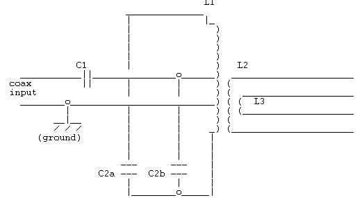
Notes:
Components are identified in the text of the article. To read the drawing (not a great production on my part!), the following comments may help:
C1 is shown here as a single section cap, but should be a *dual* section variable cap, with the second section switched in and out of the circuit in parallel with the section that is shown. (Use a s.p.s.t switch, S1, not shown.) Or switch a fixed padder in and out, as need be. Don't permanently wire the two sections in parallel, because sometimes you need a low minimum capacitance. If you use a three-section capacitor at C1, connect the second and third sections in parallel and wire S1 to switch in both of them as the high capacitance option.
C2a-C2b: dual section variable. The top of C2a goes to the top of L1. The top of C2b goes to the center tap on L1 (to which the line from C1 is also connected). The bottom (rotor/frame) of C2a-C2b goes to the bottom of L1.
The frames of both C1 and C2 need to be insulated from ground.
L1 is the tank circuit inductor. See the text for winding instructions and the tap points.
The ground connection goes to the lower of the two taps on L1 (the 5 turn point with a T-157-6 core; the 6 turn point with a T-130-6 or T-200-6 core).
L2 is the high impedance output link (10 turns), which is centered on the ground tap of L1 (5 turns on each side of the ground tap), and is interwound between the turns of L1.
L3 is the low impedance output link (4 turns), which is similarly centered on the ground tap of L1 (2 turns on each side of the ground tap), and is interwound between the turns of L1 and L2.
Use a d.p.d.t switch, S2 (not shown), to select the desired output link.
Addendum -- 160 meter mod
This is an addendum to my Z-Match article in QRP Quarterly, July 1995. It includes modified toroid winding data to use when substituting small "plastic" capacitors for the higher-capacitance air-spaced units that I used in my published design. I also make recommendations on #2 vs. #6 toroid cores, and I suggest a couple of modifications for the version of the z-match found in the Autumn 1995 issue of SPRAT. (That's the date marked on the photocopy I'm using. I believe it is SPRAT #84.)
If anyone spots any glitches in this, I'd appreciate having them called to my attention.
I can provide the original article by email, if you want a copy.
Charlie, w6jjz
clofgren@mckenna.edu
The Z-Match "Antenna Tuner": Yet a Further Update
The Z-Match design in my QRP Quarterly article (July 1995, pp 10-11) was based on the assumption that the tank circuit capacitor (C2) would be a dual section variable with at least 330 pf per section. If the capacitor instead is a small "plastic" variable of the kind marketed by Mouser and DC Electronics, then the inductance in the multiband tank circuit needs changing. The reason is that these small dual section capacitors have a lower maximum capacitance, of approximately 270 pf per section. Fortunately, their minimum capacitance is also lower, so the resulting maximum/minimum ratio allows full coverage of 80 through 10 meters, but only if the inductance in the tank circuit is properly altered.
You need to begin by selecting a toroid. I recommend a T-130-6 core, which gives better Q throughout the HF range than is attainable with a T-130-2 core. But either one is satisfactory. The important point is that the cores differ in permeability, so the number of turns will differ depending on which one is selected.
For a T-130-6 core (used with one of the small plastic variable capacitors at C2), substitute the following winding data for the data provided in my article.
L1 (the main tank coil): 32 turns of #24 enameled, tapped at 8 turns from the bottom (the ground tap) and at 16 turns (the center tap, running to C1, the series input capacitor, and also to one section of C2). The top of the winding (32 turns) goes to the other section of C2.
L2 (the high impedance link): 16 turns of #26 enameled, wound between the turns of L1, with 8 turns on each side of the 8-turn ground tap on L1.
L3 (the low impedance link): 4 turns of #26 enameled, wound between the turns of L1 and L2, with 2 turns on each side of the 8-turn ground tap on L2.
Using 4 turns for L3 permits considerable flexibility in matching very low impedances, without much degradation in the 50- 200 ohm range. (Only careful tests disclose this degradation, and it is imperceptible in practice.) However, if you wish to optimize L3 for maximum efficiency in the 50-200 ohm range, use 6 turns instead of 4 (3 on each side of the ground tap on L1).
If a T-130-2 core is used, the number of turns must be reduced, owing to the higher permeability of the core. Based on the foregoing data, I calculate the proper number of turns for the #2 core as follows:
L1: 30 turns, tapped at
7 turns from the bottom (ground tap) and at 15 turns (to C1 and
one section of C2).
L2: 14 turns, centered on the 7-turn ground tap on L1.
L3: 4 turns, centered on the 7-turn ground tap on L1.
Please note that I have derived the data for L1 when using a #2 core from the data for the #6 core, making the conversion on the basis of toroid winding formulas. If you do use a #2 core, you may wish to try reducing the total to 28 turns, tapped at 7 and 14 turns. (Because the #6 core gives higher Q, I have not actually experimented with a #2 core in my Z-Match circuit, when using the plastic capacitors.) The instructions and suggestions are otherwise the same as for the #6 core.
In my own "mini" Z-Match using the small plastic capacitors and a T-130-6 core, I have also changed the arrangement of C1/S1 (the series input capacitor and associated switch). I use a small d.p.d.t. toggle switch at S1, with a center-off position. It is wired so that in the center-off position, one 270 pf section of C1 is in the circuit. In the left hand position, both 270 pf sections of C1 are in the circuit. In the right hand position, both sections are in, plus an additional 500 pf padder (a silver mica capacitor). These options insure flexibility with unpredictable loads. In most instances, however, the arrangement in the original QRP Quarterly schematic should be adequate, even with the lower maximum capacitance of the plastic variables.
The resulting mini Z-Match has excellent matching range, efficiency, and balance. In fact, its efficiency is slightly superior to the efficiency of the units I've built using air- spaced capacitors. (This probably is because of the lower C/L ratio in the tank circuit.) Regarding the tuner's power handling ability, information on the small plastic capacitors provided to me by Roy Gregson, W6EMT, indicates it should safely handle 15-20 watts of RF, although I've only run 5 watts through it. (Keep in mind, however, that load conditions will have some effect on power-handling capacity.)
I've also enhanced the versatility of my mini-tuner by building an absorptive SWR bridge into it. Resistance values were selected so that the highest SWR seen by the rig during tune-up is about 1.2:1.
Regarding the Z-Match design in SPRAT, Autumn 1995, p 9 (which Roy, W6EMT, has worked with), I would similarly recommend a T-130-6 core, in place of the T-130-2 core indicated in SPRAT. Here, too, the change requires an adjustment of the number of turns.
For the SPRAT design but with a T-130-6 core (and using small plastic variables), I calculate the modified turns count as follows:
Main tank coil: 29 turns total (instead of the 27 turns specified in SPRAT for the #2 core). Tap at 12 and 17 turns from the bottom. The 12-turn tap goes to one section of the tank circuit capacitor, and the 17-turn tap goes to the series input capacitor. The top of the winding (29 turns) goes to the other section of the tank circuit capacitor.
Link: 8 turns, interwound between the turns of the main tank coil at the tank coil's "cold" (grounded) end. SPRAT says to use p.v.c. covered wire for the link. I doubt that use of enameled wire would make a detectable difference, but conceivably it might have a small effect on the interwinding capacitance and thus on balance with high-impedance loads.
The SPRAT circuit shows a single-section series input capacitor, but I recommend using a two-section capacitor (the same kind that is used in the tuner's multiband tank circuit), and Roy tells me that he has incorporated this modification into his Z-Match that's based on the SPRAT design. Use a s.p.s.t. switch to put the second section of the input capacitor into the circuit. (See C1/S1 on the schematic in my article in QRP Quarterly.) This will increase the matching range, especially on 80 and 40 meters. However, do *not* wire the second section permanently in parallel with the first section, because it is sometimes necessary to have a *low* minimum capacitance, and paralleling the two sections defeats this objective.
For evaluating matching range, balance, and efficiency, I recommend the tests and "Geometric Resistance Box" (tm) described by Frank Witt, AI1H, in QST, April 1995. (The tests included in my QRP Quarterly article are useful, too, but Frank's are more easily done and allow considerable precision and accuracy. Be sure to watch for his forthcoming article in volume 5 of the ARRL Antenna Compendium, in which he refines the balance test presented in his QST article.) I've used Frank's tests to evaluate my design and the SPRAT design that Roy has drawn on.
The "bottom line": My tests, as posted on QRP-L, 7/19/96, indicate that my Z-match design handles *high* impedance loads somewhat better than does the SPRAT design, in terms of both balance and efficiency. This results from the placement of the ground point within the multiband tank circuit and the availability of a separate high impedance output link. My design gives more flexibility, too, at the *very* low end of the range of impedances likely to be encountered, because of the separate low impedance output link. (The tests I posted did not cover this aspect.) In my design, the two output links and the switchable input capacitor also add versatility in handling complex loads that include varying amounts of reactance, which may throw the tuning considerably off of the settings for largely resistive loads and out of the range of a tuner with fewer options. The "price" paid for this additional flexibility is two small switches. The choice otherwise is something of a toss-up, and either design (mine or the SPRAT/W6EMT design) yields a highly serviceable and easily built "antenna tuner." As a practical matter, choosing between one or the other turns pretty much on personal inclination.
I pick my own design (surprise!) because I like to maximize matching options, even though I may seldom need to use them. I also prefer the best feedline balance I can get, even though I know from computerized antenna/feedline modeling that--within limits--feedline imbalance generally has little effect within commonly-used wire antenna systems. So perhaps it's aesthetics. For the same reason, others may place a higher value on lean simplicity and thus choose the "competition."
Thanks to Fred Bonavita, W5QJM, and Pete Hoover, W6ZH, for continuing to send me copies of "tuner" articles they encounter in various publications; to Fred again for providing the "plastic" capacitors I used in my mini Z-Match; and to Roy Gregson, W6EMT, for several informative email notes on the SPRAT design and Roy's own experiments.
Charlie Lofgren, W6JJZ
7/21/96
1934 Rosemount Avenue
Claremont, CA 91711
909-626-6731 (h)
909-621-2931 (w)
clofgren@benson.mckenna.edu
Z-Match on 160 meters?
On Thu, 16 Jan 1997, John Seboldt, K0JD, asked:
> The big question is: if I adapt my QRO components for 160 meters, what might be the best approach? Add more capacitance with the same coil? Rescale the whole thing for 1.8-20 MHz or so, and not expect the highest HF bands?
I use a z-match to tune a 110' centerfed wire (with about 45' of 450 ohm ladder line) on 160 thru 12 meters. (As for whether this is a good antenna system on 160, see below.) The circuit is the same one described in my e-mailable packet of z-match material (same, too, as in the article in volume 5 of the ARRL Antenna Compendium (just out)), but with the inductance of the main tank coil increased about four times, and the links increased too. You could do the same thing by doubling both the inductance of the coil and the capacitance of the double section tuning capacitor, but a cap to accomplish the latter is hard to find. (And quadrupling rather than doubling the inductance theoretically gives a better L/C ratio in the tank circuit in terms of efficiency.)
In the unit I'm using, the inductor is 36 turns on a T-157-2 core, with the center tap at 18 turns (!) and the ground tap at 9 turns. The high impedance link is 16 turns, and the low impedance link 6 turns. The cap is about 365 pf per section. The low band tuning range covers 160-40, and the high band range 40-12. I won't vouch that the coverage would extend this high with all antenna systems. (The magnitude and composition of the complex impedance at the system's tuner feedpoint will make a difference.)
You could probably use the same approach on Roy Gregson's ZM-1, but as I recall the ZM-1 comes with a T-130 core, which would make for a tight fit for the necessary turns.
As usual: Anyone one who wants my z-match packet, just drop me an email note and I'll send it by reply email.
(Incidentally, lest someone think I'm loonier than I really am, I don't mean to say that a 110' center-fed wire is a very good antenna on 160. It isn't. In fact, it's downright crummy. But it's what I currently have--and the station ground isn't good enough to feed it as a T on 160--and the z-match tunes the system.)
72,
Charlie, w6jjz
clofgren@mckenna.edu
![]()
![]()
![]()
![]()