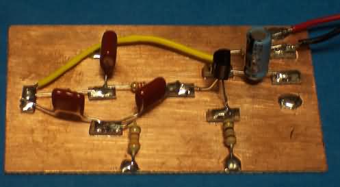
An
NJQRP "mini-kit" ...

Good
Enough Oscillator = GEO
"Good
Enough Oscillator"

Designed
by Joe Everhart, N2CX
n2cx@voicenet.com
Limited
kitting for NJQRP members attending the meeting of Aug 9, 2003
“Scientists want perfection, hams
make things that are good enough
to work.”
•“Almost
calibrated” output level!
• In
the ballpark output frequency!

The basic oscillator uses a common-emitter
configuration. Feedback is
provided by a network composed of two “parallel tee” networks, R1/C1/C2
and C2/R3/C3. This twin-tee
network has the characteristic of providing a notch at a certain frequency
along with a 180-degree phase shift. This
phase shift exactly matches the opposite phase shift produced by the
transistor. Thus feedback is
provided which makes the circuit oscillate.
Resistors R1 and R2 also provide a base bias current for the
transistor. Resistor R4 is a
collector load and R5 adds some negative feedback to stabilize the circuit.
Resistor R4 can be changed to set the sine wave output level.
The less resistance, the higher the output and vice versa.
However if it is made too low, there will be too little gain for
oscillation.


Last Modified: Aug 9, 2003
![]()
![]()


![]()