 PIC-based APRS Weather Station
|
|
|
PIC
APRS ~ Part 3 Files ~
All
Software Files |
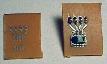
Part 3 - Temperature & Humidity Hi gang! Finally, after laying the groundwork in the first two episodes of the PIC WX saga, its time to get down to the business of actually measuring weather data! Were going to start by adding a sensor for temperature and relative humidity. The sensor Ive chosen is the SHT11 from Sensirion (www.sensirion.com). The SHT11 is a digital device that, when queried, returns an unsigned 16-bit number that must be converted into the actual value for temperature or humidity by using simple formulas given in the SHT11 data sheet. It requires no calibration and is reasonably accurate (for temperature, better than ±3.6 °F between 40 and 100 °F, and ±3.5% for relative humidity). Purchasing information is found on Sensirions web siteits around $20, but you can also request a free sample (mine arrived within a week of my request). The SHT11 sensor is pretty smallonly 0.3 by 0.2, basically in a surface-mount package. The pin spacing on the package is 0.05. Because of this, I fabricated a small PC board on which to mount it so that it would be easier to handle. Figure 1 shows the PC board before and after the SHT11 was mounted. I included pads for 0.1 header pins to make it easier to connect the board to the rest of the circuit. I made several extra PC boards for the SHT11, so contact me if youre following along and need one.
Figure 1. The carrier board for the SHT11 sensor. The data sheet for the SHT11 cautions that care must be taken when soldering the sensor. Contact time must be limited to 5 seconds with an iron at 350 °C. In addition, the sensor should be stored for at least 24 hours at a relative humidity of 75% or higher after soldering to allow it to recover (since its always dry here in Colorado, I stored mine in a small container with a wet sponge). Although the SHT11 has eight pins, only pins 1 through 4 are actually used:
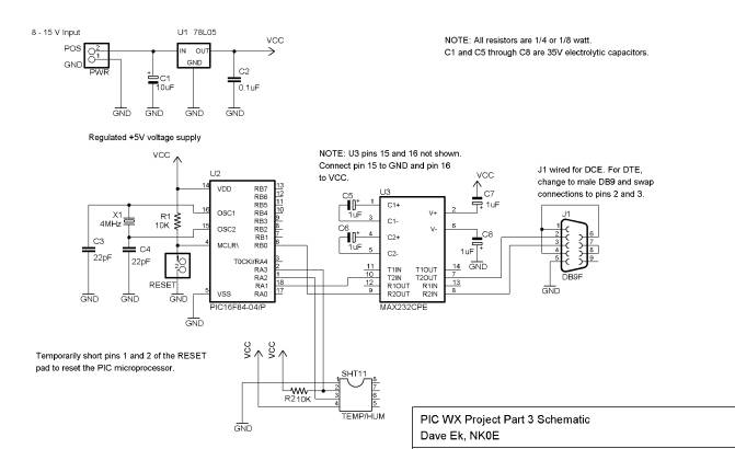
You probably figured out for yourself that pins 2 and 3 must be connected to the PIC chip so that the PIC chip can communicate with the SHT11. The PIC and SHT11 communicate using synchronous serial communicationssynchronous because they share a clock line (SCK) to indicate when each bit can be written/read. The PIC chip controls the SCK line, while the PIC and the SHT11 take turns controlling the DATA line. The PIC uses the SCK line to signal when each bit can be written or read. Although its called a clock line, it doesnt need to have a fixed frequency. When the clock line goes high, a bit can be read from the DATA line. When the clock line goes low, a bit can be written to the DATA line. In other words, the device currently sending the data should set the value of the DATA line whenever the clock line goes low, and the device reading the data should get the value of the DATA line whenever the clock line goes high. The PIC chip controls this line at all times. There is no danger of the PIC chip changing the clock line at too high of a frequency for the SHT11the maximum clock frequency for the SHT11 is 10 MHz, while the PIC can change it at a maximum frequency of only 1 MHz (determined by its own clock rate of 4 MHz). The SHT11 datasheet covers the operation of the sensor in great detail. In a nutshell, here is the sequence of events for obtaining a reading from the sensor: 1) The PIC chip sends a transmission start sequence. While SCK is high, the DATA line is taken low. While the DATA line is low, the SCK line is taken low and then high again, and then the DATA line is taken high. This signals the SHT11 that a command will be sent to it. 2) The PIC chip sends an 8-bit command. 00000011 is sent if temperature is desired, or 00000101 is sent for humidity. 3) The SHT11 acknowledges receipt of the command by pulling the DATA line low for one clock cycle, and then releasing the DATA line (which goes high). 4) After it has completed its measurement (which can take up to 210 ms), the SHT11 again pulls the DATA line low to indicate that its ready to send data back to the PIC. The data is returned as three bytes (high byte, low byte, checksum). After receiving each byte, the PIC must acknowledge by pulling the DATA line low for one clock cycle. Figure 2 shows the schematic diagram for the entire circuit. It differs from the schematic for the previous installment only by the addition of the SHT11 sensor. Note that the DATA line for the sensor has a pull-up resistor connected to it. The SHT11 datasheet indicates that the pull-up resistor is necessary.
Figure
2: PICWX schematic for part 3 To convert the five-digit numbers to temperature and humidity, use the following formulas (also given in the SHT11 datasheet):
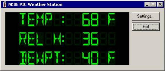
In those formulas, temperature T is given in degrees F, and humidity H is the percent relative humidity. N is the number returned by the PIC chip. If you examine the PIC code, youll see that the t and h commands reuse the same code that communicates with the SHT11. I wrote several subroutines, to send the command to the SHT11, get a byte from the SHT11, and acknowledge bytes received from the SHT11. I also reused the code from last time that converts a two-byte binary integer to an ASCII string and sends the ASCII string back to the PC. Finally, I wrote a simple Windows program (using Microsoft Visual C++) that periodically queries the PICWX for temperature and humidity and displays it on the screen. A screen shot is shown in Figure 3. When you first run it, click the Settings button to tell it the serial port to which the PIC WX circuit is connected, and also to set the measurement intervals. When you start the PIC WX program, it places a small thermometer icon in your system tray. If you hover your mouse pointer over that icon, a small box will pop up that shows the current measurements. If you minimize the PIC WX program, it disappears completely except for the icon in the system tray. Double-click the icon to make the PIC WX program reappear. You can download the PIC WX Windows program here.
Figure
3: The PIC WX Windows program for reading the PIC weather station. That wraps up this installment of the PIC WX project. Next time well add a sensor for wind speed. Thatll probably be a bit more complicated than the SHT11 sensor! 73,
Dave NK0E
Page last modified:
January 22, 2003
|
.gif)