Hello
DDS
Using "Template" to make your first program
The heart of the Breadboard project is the HC908 Daughtercard, providing
8MHz of 8-bit computing horsepower with 32 kilobytes of flash memory, a
built-in RS-232 serial port for loading new programs, and lots of I/O to
control just about any QRP project we might need on our bench. This
daughtercard has been long in becoming available, and all 300 of those who
ordered the assembled and fully tested unit now have this little gem in
their hands. I do appreciate
everyones patience and support along the way, and promise that youll
find the wait was worth it. In
addition to being able to load and run all of the software programs
described in previous issues of this column, we next embark on a journey
guaranteed to excite the homebrewing hormones in your bloodstream.
Hello DDS
The first program one usually creates on a new platform is Hello
World! This simple program
merely displays a message to the console indicating that it is alive and
that the assembly and download process works. As readers know, the HC908
Daughtercard already comes with a pre-loaded monitor program (HCmon)
that is controlled by a serial terminal, as well as a pre-loaded
exerciser program for the various I/O devices you might have hooked
up. What well do next is create a new program called Hello DDS to
show how easy and straightforward it is to use the built-in subroutines
provided in the Exerciser to enable you to produce your own first program.
Hello DDS is a simple terminal-driven program that prompts the user
for the frequencies desired to be generated by the DDS Daughtercard
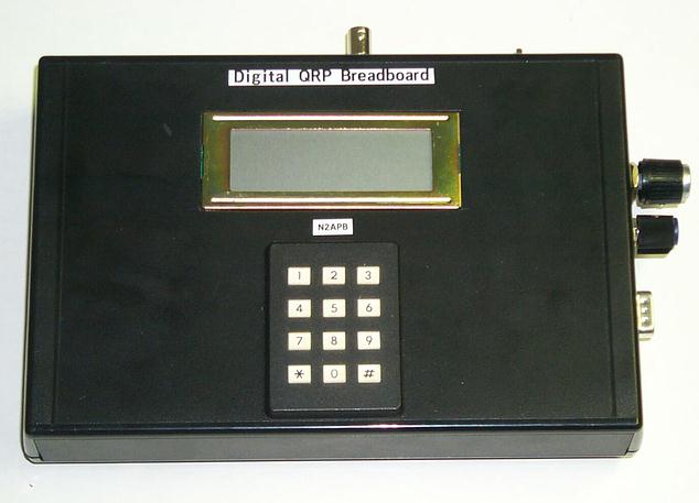
connected to the HC908. As can be seen in Figure 1, the system is very
easy to assemble. The minimal breadboard consists of the HC908
Daughtercard connected toan RS-232 serial terminal. Ive used my PDA (a
Palm Tungsten W) as the terminal, although you could use any terminal that
has a serial port e.g., a PC running HyperTerm, a Poqet Plus notebook
computer running ProComm, or anything in between. Using a PDA is a
convenience that allows me to more easily use projects when hamming out in
the field or when on business trips.
The DDS Daughtercard is connected to the HC908 card using only
three wires for the serial loading protocol and two wires for power and
ground. (See the notes
section at the end for details on this card.) A 9V battery powers both
cards and the PDA terminal plugs into the HC908s built-in serial port.
The schematic of this configuration is merely a simple subset of those
published in previous issues of the column, and on the projects
website, so it will not be repeated here.
When powered on or when reset, the HC908 card sends menu text to
the PDA prompting the user for a command. As shown in Figure 2, he has a
choice to:
1)
Enter a freq sends the specified frequency to the DDS chip
2)
Set start freq specifies the starting frequency for a sweep
3)
Set end freq specifies the ending frequency for a sweep
4)
Set step size specifies the step size to be used during the
sweep
5)
Sweep DDS commands the sweep to begin
Creating Hello DDS
Now that you see what the end goal is, lets go through the
process of actually creating the HC908 program that does this.
Experienced software developer knows that the best way to create a
new program is to start by modifying an existing one. Well use the Exerciser program as the starting point for
nearly all our programs on the Digital Breadboard project, as it provides
a convenient template for program format, interrupt processing, timing and
access to commonly-used subroutines. To emphasize the value of this
approach, Ive provided a stripped-down version of the Exerciser
program with the HC908 Daughtercard product itself, as well as on the
Digital Breadboard website. (Recall that absolutely all software and
hardware used in the Breadboard project is freely available for anyones
non-commercial use.) This Template.asm file is where all our edits will be
done.
With no modifications, the Template program merely provides the
interrupt hooks and common subroutines, as well as the interrupt structure
for the heartbeat LED. This blinking LED on the HC908 card is a good
indicator that your program is running satisfactorily (e.g., that it
isnt hung up in an endless loop someplace.)
If the Template program is downloaded to the HC908 card and run
as-is, all youd see is the blinking heartbeat LED with no other
activity happening on the console, LCD, shaft encoder, DDS or anything.
Try it and see!
This is the main area of interest for us in the code:
User_Main:
ldhx #TemplateBanner_msg
jsr _puts
;print the Banner message
Main_Loop:
sta
copctl ;clear
the COP counter
bra
Main_Loop
TemplateBanner_msg:
fcb Template Program,CR,LF.0
What well do is place the new/modified program below in its entirety
with line numbers that we can reference to help explain the program
operation.
1
User_Main:
2
ldhx
#DDSmenu_msg
3
jsr
_puts
;print the Banner message
4 Main_Loop:
5
sta
copctl ;clear
the COP counter
6
ldhx
#Command_msg ;point to the Command string
7
jsr
_puts
;and print it to the terminal
8
jsr
_gets
;get an input command
9
lda
_inbuf ;get
the entered character
10
cmp
#1
;compare the input to 1
11
beq
Set_Freq ;if it was a 1, branch to
12
; the routine to set freq
13
bra
Main_Loop ;go
get another command
14
15 Set_Freq:
16
ldhx
#EnterFreq_msg
;point to the Enter Freq string
17
jsr
_puts
;and print it to the terminal
18
jsr
_gets
;get a sting of numbers
19
jsr
Set_DDS
;set the DDS output to that freq
20
bra
Main_Loop ;and
go get next command
21
22 DDSmenu_msg:
23
fcb
HELLO DDS v1.01,CR,LF
24
fcb
1) Enter freq,CR,LF
25
fcb
2) Set start freq,CR.LF
26
fcb
3) Set end freq,CR,LF
27
fcb
4) Set step size,CR,LF
28
fcb
5) Sweep DDS,CR,LF,0
29
30 Command_msg:
31
fcb
CR,LF,Command: ,0
32
33 EnterFreq_msg:
34
fcb
CR,LF,Enter Freq: ,0
The first thing well do is change the pointer to display a new set of
text that represents the menu. Line 2 points to the new string to be
output DDSmenu_msg at line 22. The
call to the _puts (put string to console) routine then sends all the
characters of those six fcb lines to the terminal and only stops
when it sees the 0 terminating character.
The program continues running at label Main_Loop (line 4), and
accesses the copctl (Computer Operating Properly) control address, which
resets the watchdog timer and prevents the program from automatically
locking up.
Next, we added a couple of lines (6-7) to print the prompt
Command: , and added line 8 (jsr _gets) to get a user input string.
(We wont do advanced things like range checking for valid
entry.) The user input string
is terminated when the <ENTER> is pressed.
Next we check the command character entered (located in _inbuf)
against the valid commands and branch to the appropriate desired routine
when a match is found. (Well
only show one such command check. The full program listing at the end will
show all command checks.) Lines
10-11 compare the input command to a 1, and if it was found to be a
match, the Set_Freq routine is called.
Otherwise, if no match was found, we instruct the computer to go
back to the Main_Loop label and prompt for a command again.
Assuming a valid command was found (1 in this limited case),
the program execution jumps down to continue running at the label Set_Freq
on line 15. The user is
prompted for entry of a frequency string at lines 16-17 which displays a
line of text at label Enter_Freq_msg, and the program waits at _gets
(line 16) for a full numeric string to be entered.
Once the user hits <ENTER> to end the frequency string entry,
the program calls a library routine Set_DDS on line 19.
This routine converts to binary the frequency string residing in
_inbuf and sends the appropriate control word to the DDS, thus
setting the DDS output to that specified frequency. Once that has been
accomplished, line 20 instructs the computer to prompt for another command
again.
That Wasnt Hard
Was it?
Those readers not into software, not even the least little bit, probably
skipped over the last section and rightly so. For many of you, the joy is not in creating new capabilities,
but in using the existing ones. Whatever
your preference, this Hello
DDS program is still for you because you can have fun creating and
modifying the Template as described, or you can just download this program
from the Digital Breadboard website, load it into your HC908 card and use
it directly. Its that
simple. Bit no matter which route you follow, youll end up having
a new program for your HC908 Daughtercard that can serve an important role
on your bench generating useful frequencies for test, measurement and VFO
control.
HC908 Test Fixture
I wanted to quickly show you the test fixture that I used to
initially program and check out each of the HC908 Daughtercards before
shipment. Besides just
wanting to show off some of the evolutionary stages of developing this
heart of the Digital Breadboard, I also wanted to give you some ideas on
how you might package the HC908 card in a functional system.
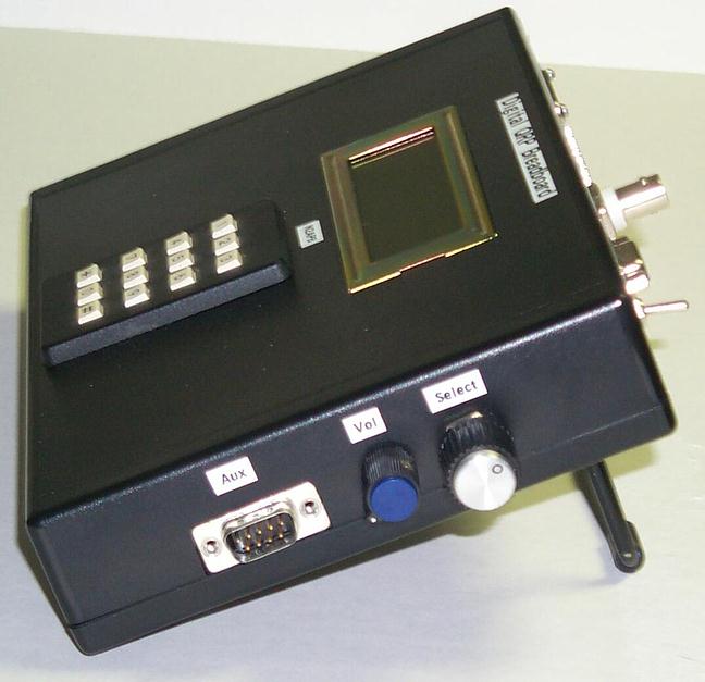
Figure 4 shows an enclosure containing the HC908 Daughtercard-under-test,
with a variety of I/O peripherals mounted on the board. The voltage
regulation is in the upper left corner, and the boot programming connector
is in the lower right. The
bargraph LEDs are used to visually indicate that the the plethora of I/O
bits operate properly during Test Program execution. The LCD, the DDS
daughtercard, the shaft encoder (with the knob), the potentiometer in the
bottom right, and the little switch in the middle-right of the board
(serves as the Monitor Jumper to control whether the unit powers up
into the Monitor or into the User application) all serve to test the
capabilities of the HC908 Daughtercard.
This test fixture also served as my development platform for the
Antenna Analyzer II derivative of the Digital Breadboard before the
dedicated AntAnal hardware was available.
You too could use such a platform in the development of your own
custom projects. Just
thought.
Until Next Time
The ideas and examples presented this time certainly give owners of
the HC908 Daughtercard lots of ideas to be working on for another couple
of months. Even readers without the HC908 platform can get a fairly good
idea of the flexibility and utility of the hardware/software provided in
this project. Check the
Digital Homebrewing website often, as new material is being added at an
increasing rate now that were over the daughtercard availability hump.
Theres lots of fun ahead as we finish off the Antenna Analyzer
and present the completed project (and kit) in the enxt installment. Until then, happy QRP computing!
Page last modified:
April 2003
Copyright 2003 G. Heron, N2APB
|
 Digital
QRP Breadboard
Digital
QRP Breadboard 