 Digital
QRP BreadBoard
Digital
QRP BreadBoard |
Digital
QRP BreadBoard |
|
Digital (column #5) These are the latest project files:
Schematic
- sheet 1
Schematic
- sheet 2
"HCmon"
Debug Monitor
Original (larger) Enclosure:
Latest (smaller) Enclosure: (To be posted soon)
Production Daughtercard:
Back
to
|
Baseboard
& Enclosure The Digital QRP Breadboard project has come a long way in four issues! As chronicled so far, weve presented modules for the brains (microcontroller), the eyes & ears (LCD and keyboard), and the voice (precision frequency source). Weve even created a special reflectometer to measure SWR and a software voltmeter to get the readings into the system. Now its time to pull it all together to create the first instance of our full-blown, high-performance Digital Breadboard system. Many readers have asked about the big picture for this adventure ... well, here it is! We'll
start out by discussing the enclosure and form factor, and then go through
a functional inventory of the whole project. Software is then overviewed,
showing how all components are made to dance in unison to create an
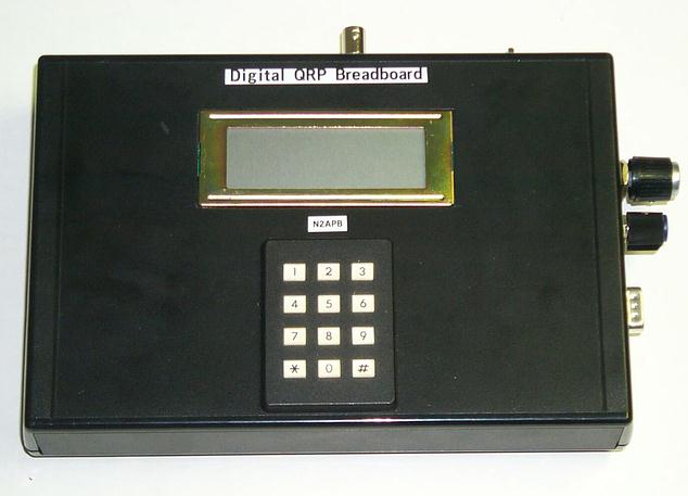
extremely flexible and powerful device for your ham shack. Enclosure
& Form
Factor A
project's form factor is the way
the hardware modules are physically constructed and integrated as a whole. As the Digital Breadboard evolved over the last 12
months, I described that the various functional modules would be provided
as small plug-in daughtercards to help with re-use and upgrade of the
specific functions like the DDS, reflectometer, audio amplifier and
others. I started laying out the baseboard pc board containing these
daughtercards, but it quickly became apparent that this approach would be
more expensive as compared to designing a single, integrated PCB
containing most of the functionality. In
order to keep the cost of this project as low as reasonably possible, I
therefore opted to design most modules directly into the layout for the
baseboard, except for the HC908 microcontroller and the DDS chip. The 68HC908AB32 will continue
to be provided as a daughtercard in part for those who have already purchased
it along the way, as well as because the microcontroller surface mount
package cannot easily be attached by homebrewers. Its also a very
useful module that can be used other projects when kept in this small
daughtercard format. The DSP chip (AD9850 from Analog Devices) is also provided as a small plug-in daughtercard. The card provides the DDS chip, clock circuitry, a 5th-order elliptical low pass filter, an 8dB MAR-3 RF amplifier, and onboard voltage regulation. This board is provided as a daughterboard plug-in to allow the user to change or upgrade to using a different DDS in the future, if desired. Further, the DDS Daughtercard may easily be used in other projects controlled by other microcontrollers or even by a PC over its parallel printer port. (The DDS Daughtercard will be available in January 2003.) Thus,
the Breadboard now consists of a 3" x 5" baseboard containing most of the circuits,
connectors/controls, LCD, keypad, and plug-in modules for the HC908 Daughtercard and
the DSP daughtercard. This
isnt too much of a deviation from our original course, and I think most
will appreciate the lower cost of the ultimate system. To retain the
flexibility of being able to replace or upgrade any given module, even
though its integral with the baseboard, Ive layed out each module
such that its I/O signals are conveniently located in one spot. This way,
should you decide to upgrade your audio amp (for example) to a
bigger/quieter version, all youd need to do is slice some traces at the
indicated points, insert a pinheader at the modules I/O pads, and plug
your own custom daughtercard onto the baseboard above the existing audio
amplifier
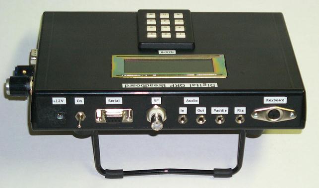
circuit. As mentioned on the Home Page, we're trying to make this whole project even more immediately and ergonomically useful, and we've decided to make the first instance of the Digital Breadboard in the form of the "Antenna Analyzer II". The PC board is being layed out to fit into a 3.5" x 7.5" HPL-9VB plastic enclosure from PacTel which is a much better size for a handheld portable measurement instrument. The only Breadboard features we're sacrificing at first is some board space for the extra connectors, prototyping space and the spot for the DSP daughterboard. See the dedicated AntAnal web pages for complete functional description of the capabilities being provided in the first form of the Digital Breadboard kit. Breadboard Functional Blocks Referring
to the schematics, lets go through a module-by-module inventory of the
Digital Breadboard and see what functionality we have in place as a system. HC908
Daughtercard The brains of the Breadboard is contained in this
removable microcontroller daughterboard which holds the
powerful-yet-inexpensive 68HC908AB32 microcontroller by Motorola, with
lots of memory and I/O, and peripherals like counter/timers, asynchronous
serial ports, and A/D converters. The HC908 daughterboard also contains
the clock, reset pushbutton, voltage regulator and RS-232 drivers. As
previously discussed in detail, the software supplied with the project
allows for easy self-programming of the chip just download new
software programs to the chip and it burns the code into its flash memory.
No need for special, expensive or complicated programming hardware with
this project!
By the way, you can find the HC908 Daughtercard schematic in the
second installment of this column (QQ for January 2002). Its also
available online at the projects website see the References section
at the end of this column. DDS
-- The Analog Devices AD9850 Direct Digital Synthesis (DDS) chip is
used to generate frequencies for stimulus, analysis and measurement.
Signal generation is possible from the sub-Hertz region to over 30
MHz, providing the Digital Breadboard with a superbly-precise, accurate
and software-controllable source of stable signals for use in a variety of
experiments. The DDS module includes a 100 MHz oscillator to drive the
clock input of the Analog Devices AD9850, thus enabling the device to
generate a maximum usable frequency of 30 MHz. A 5th-order
elliptic filter is used on the output of the DDS to ensure that a clean
sinusoidal signal of about 750 mV is produced.
This signal can be configured to go directly to the BNC at the edge
of the board or go on for additional processing. RF
Amp
Since the DDS puts out a relatively small signal all by itself, a
Mini-Circuits MAR-3 amplifier is optionally provided in the path to boost
the signal and make it more useful in a reflectometer application. This
tiny amplifier provides 8 dB of gain, as set by the bias resistor and
inductors on the common output/bias port, and enables the reflectometer in
the following stage to achieve better low signal performance. The builder
may configure this amplified RF signal to be routed to the BNC connector
or go on for yet additional processing. Reflectometer
The reflectometer, or SW bridge, was presented in the last issue of
this column. The middle 1N34 diode samples and rectifies the AC imbalance
in the Wheatstone bridge to produce a DC representation of the signal
reflected back from the output circuit on the BNC connector (e.g., an
antenna system.)
The other two diodes sample and rectify the forward path and the
load side to produce voltages representing the forward signal and the
impedance, respectively. The three DC voltages are presented to the next
stage for buffering and amplification. Compensation
& Buffer Amplifiers This two-stage module utilizes true
rail-to-rail op-amps for better low-signal performance.
The first stage in each signal path employs another 1N34 diode as
its feedback element of a unity gain amplifier to compensate for the
nonlinearities of the diodes in the previous stage. This enables the
component measurements to be much more accurate at QRP levels. The second
stage boosts the voltage to better match the 5V full scale range of the
A/D converter of the HC908.
It also transforms the low impedance of the first stage to about
100K in order to present a better condition to the 10K-ohm input impedance
of the A/D. Liquid
Crystal Display (LCD)
LCDs have become commonplace in our microcontroller projects. The
Digital Breadboard uses an inexpensive 4-line by 20-character/line device
to display status and measurement information to the user. The software
driver for this display assumes that a common HD44780 controller-based LCD
is used, so one could actually use a larger or smaller LCDs fairly easily
instead of the specified one. One could also upgrade the Breadboards
capabilities to use a graphic LCD with an appropriate software driver in
place. Keypad
A 12-button keypad is provided on the Digital Breadboard to give
the user an ability to perform direct numeric input. This is useful in VFO
frequency-setting applications, or for configuration and data entry
situations.
The keypad also serves as a splendid set of general purpose
pushbuttons that can be assigned whatever function desired by the user.
Hence there are no other separate pushbuttons provided in this project.
Whenever a key is pressed, an interrupt is issued in the HC908 and
the software scans the 4 row x 3 column switch matrix to determine which
key has been actuated. This key code is returned to the software routine
that is expecting the input. Keyboard
A standard PS2-style keyboard, similar to many keyboards used on
PCs these days, can be used with the Breadboard. The importance and
utility of this input device will become more apparent in the near future
when we introduce the final module, the DSP Daughtercard.
This combination of DSP co-processing and fast alpha-numeric input
by the operator is the basis for PSK31 and other digital modes intended to
be supported by this project. The Dauphin keyboard used with the prototype
Breadboard thus far, as pictured in previous columns and on the website,
is a small PS2-style keyboard that is ideal for portable use with the
project. The
NJQRP has acquired a number of these neat little keyboards and will
provide them with the Breadboard system when we begin production. DSP
Daughtercard Perhaps the final major hardware module currently
being designed for the project is a daughtercard containing a DSP intended
for audio processing.
One of the many goals for the Breadboard continues to have it
perform as a stand-alone digital mode controller, allowing the user to
communicate using PSK31 (et al) without the need for a completely
dedicated PC.
This DSP card, initially containing an Analog Devices ADSP-2189
digital signal processor and mating codec (integrated A/D and D/A
converter), is fast enough to demodulate the audio signals coming from
your transceivers speaker, and then simultaneously modulate the data
you type on the alpha keyboard and send that audio out for input to your
SSB rig.
The DSP Daughtercard is being designed right now and will be presented in
2003. Prototyping
Area Although difficult to show on a schematic, the Breadboard PCB
is being layed out to provide a small area approximately 2 x 2 that
is populated with plated through holes. Looking like perforated
breadboard, this area can be used for personal experiments involving
components not already provided on the Breadboard PCB. Further, all of the
extra/unused signals are brought to the edge of this prototyping area so
the homebrewer may wire-in any of the 13 available HC908 I/O pins for
specialized purposes.
Alternatively, or in addition to using hard-wired components in
this proto area, the homebrewer could fabricate a small board to fit into
those signal pads at the edge of the area, effectively producing a
replaceable prototyping daughterboard that could be added/removed as the
application warrants. Does this Digital Breadboard have flexibility?
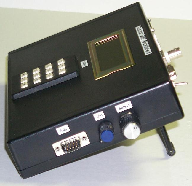
You bet! Miscellaneous
Circuits A shaft encoder provides ultimate flexibility to the
operator as a continuous rotation menu selector, numeric dial setting,
frequency tuning, and so on. An input conditioning circuit serves as a
front end for an electronic voltmeter and RF probe by presenting a
buffered AC or DC signal to an A/D input on the HC908 card. A frequency
counter function is provided by having a transistor shape the sinusoidal
waveform input to a pin on the AUX connector before presenting the signal
to an edge-sensitive counting input of the HC908.
Software determines the period of the applied waveform and the
frequency is then calculated.
A Morse paddle may be connected to an input jack and software on
the HC908 performs as an iambic keyer, which in turn drives an external
transmitter through the Keyline output jack.
A tone is also sounded, under control of the HC908, and is output
through an LM386 audio amplifier.
This audio tone can be the sidetone for the keyer, the output for
an Audio Voltmeter (see the N2CX article concerning such a project
elsewhere in this issue), or mode confirmation beeps.
Finally, room is provided within the Digital Breadboard enclosure
for a ten AA cell pack, thus providing portable power for the field use of
the unit. Software: The Master Program, HCmon Debug Monitor and the Exerciser Master Program
As
mentioned at the start, software running in the HC908 microcontroller
makes all these hardware modules dance in unison to perform the various
functions we want in the radio shack.
The Master Program performs as a real time executive upon which all other functionality and software
operations are inserted. As more features and capabilities are added to the
Digital Breadboard, the software to control them will be merely added to
this existing framework to provide an ever-growing, ever-capable list of
menu items from which
the operator can select. Exerciser
A
Main Menu is presented to the user on the LCD and all menu items are
presented by rotating the Select control (shaft encoder). When
the desired menu item is displayed, the user depresses the Select control or the
asterisk button on the keypad to select that item. Oftentimes a menu item
has sub-menus to allow the user to select various options for the chosen
operation.
This user interface is quite intuitive, easy to learn and quick to
use. The
following functions and capabilities are present in version 1.0 of the
Exerciser software:
VFO, Voltmeter, Freq Counter, SWR Bridge, Freq Sweep, Impedance,
Keyer, Keypad Test, Keyboard Test, LCD Test, A/D Calibrate, Serial Port
Test and Program Load.
This software comes pre-programmed on the HC908 Daughtercard, and
it may be re-programmed locally by downloading the file from the
Breadboards website and using the Program Load menu item with
your PC connected to the RS-232 serial port.
(This self-programming feature was described in previous columns
and is on the website.) Debug
Monitor "HCmon"
This program is a simple, low-level debug monitor developed to support any
project based on the HC908 Daughtercard. The operator interfaces to the
HCmon by means of a dumb terminal connected to the RS-232 serial port of the MPU
daughtercard. Through the Monitor's command/response structure, the operator may edit
memory and MPU registers, set and reset breakpoints, "go" or single step from any executable location in the loaded program, load S record files
sent by the terminal, program Flash memory from the downloaded S records, and read input ports and set output ports. Whats
Next? Well,
there you have it the completed first version of the hardware!
It took five issues to bring the project to this point but there
was plenty to chew on, absorb and try out along the way.
We need some time now for the hardware
availability to catch up with the prototype system developed to this
point, so the next several columns will be devoted to software what
makes this Breadboard tick and how you can use what we have so far.
This will give the development team some time to catch up on making
the baseboard PCB available and smoothing out the software so everyones
experience with this project will be very positive. After all, the end
goal is to have a single box like this in the shack that can perform a
multitude of functions merely by selecting the right menu item or by
loading new software. In order to make it easy for the user, lots of work
is needed behind the scenes
and were dedicated to doing it right!
Page last modified:
December 26, 2002
|