 Digital
QRP BreadBoard
Digital
QRP BreadBoard |
Digital
QRP BreadBoard |
|
BreadBoard (column #3)
BreadBoard
photo
BreadBoard
photo
BreadBoard
photo
BreadBoard
Schematic
BreadBoard
Schematic
Back
to
|
Adding
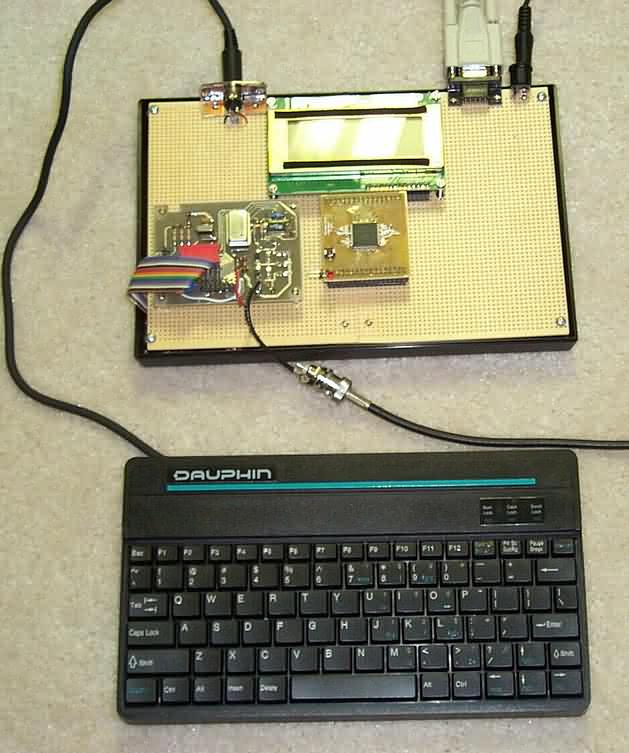
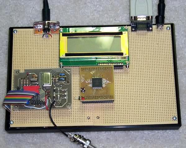
Frequency Synthesis with DDS So far in our evolving BreadBoard project weve presented the overall block diagram of the design, the first instance of project hardware in the form of the HC908 microcontroller Daughtercard, keyboard interface and LCD for I/O, and the first hardware-software application - a scaling voltmeter. If youve been able to build along with us you have the start of a powerful and flexible little station accessory. This time, leveraging the Direct Digital Synthesis technology we presented in the Spotlight section of the January 2002 issue, well add a DDS to the BreadBoard to create a basic VFO. Sharp readers will note that weve been dropping hints relative to an approaching milestone, and this DDS VFO brings us a huge step closer to realizing it. I dont want to say too much more right now, but most homebrewers will want to keep up with the BreadBoard project in order to easily bring it all together later this springtime. In a nutshell, this installment adds a digital VFO to the BreadBoard in order to generate good sine waves ranging from one Hertz up to 20 MHz. We accomplish this by employing the AD9850 DDS chip from Analog Devices and an output filter to eliminate the aliasing signals, thus producing a fairly good waveform that can be used as a test signal or as a local oscillator in a transceiver. Here's a photo of the overall BreadBoard showing the keyboard and all cabling connected. In a photo of the BreadBoard itself, you see the IBM keyboard connector at the top left and the 12V power connector and RS-232 connector (for programming interface to a PC) shown at the top right. A 4-line LCD is in the top middle, with the HC908 Daughtercard below it. The DDS VFO board from FAR Circuits is shown to the left. A simple 3-wire serial interface links the HC908 Daughtercard with the DDS chip. This enables the VFO software running on the microcontroller to load the DDS control registers with specific values that set the precise DDS frequency. Building
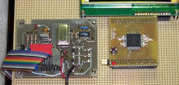
the DDS VFO Board However for the short-term breadboarding and experimentation needs in this project, weve employed the DDS VFO pc board used by Curtis Preuss, WB2V in his landmark QEX article from 1997. This inexpensive pc board is available from FAR Circuits and contains the near-minimal amount of circuitry required for our application. Most importantly the DDS VFO board has the pc traces for the surface mount DDS chip, enabling us all to easily use the DDS chip within our homebrew BreadBoard. As can be more clearly seen in this photo, the DDS VFO pc board is mounted to the left of the HC908 Daughtercard. We get the three control lines over to the DDS board by means of a ribbon cable that plugs into the unused 18-pin IC socket. Ground and +5V wires are conveniently contained in that same ribbon cable. The RF output from the board is provided by way of a short piece of RG-174U mini coax terminated in a BNC jack. A standard BNC patch cable is shown taking the signal ultimately to an oscilloscope for monitoring. Hardware Circuit Description Please refer to the large schematic in Figure 7 for this discussion. We have the same HC908 Daughtercard interconnect as used last time. After all, were merely adding on to the current design, once again leveraging the AT keyboard and LCD as the system I/O and user interface. Similarly, we again need the RS-232 serial connection to the external PC in order to burn the new DDS VFO program into the HC908 microcontroller. [Recall that everyone is able to download new software programs from our Digital QRP Homebrewing website and directly program the microcontroller without the need for any special programming hardware. The bootstrap program provided in all new HC908 Daughtercards provides the protocol for downloading and burning new software into the microcontroller directly from ones PC. Thus, whenever we introduce new software features or updates, youll be able to quickly and painlessly get it loaded into your BreadBoard.] Last time we described some analog signal conditioning components for measuring voltages. These functional blocks are shown in dashed boxes connecting into Port B0 and B1. Refer to our last column or to the online website for those details ... dont forget to include them when building up your BreadBoard, as well be using them again shortly. The DDS circuitry that well be using this time is shown at the bottom of the schematic. The AD9850 contains a 32-bit phase accumulator, a 14-bit lookup table and a 10-bit D/A converter. It can be clocked at 125 MHz to produce a 41 MHz sine wave output, although well use the 66.666 MHz can as a commonly available oscillator for now to generate a top frequency of 20 MHz. (Be sure to use a socket to mount this can in the pc board so we can later substitute a higher frequency oscillator to allow us to generate up to 30 MHz in our mystery application coming soon!) A 40-bit control word is serially loaded into pin 25 using pin 7 as the data write clock. By toggling pin 8 the input register is shifted to the DDS core. The 40-bit control word contains a 32-bit frequency, 3 control bits and 5 phase modulation bits. These bits determine the generated frequency and some software calculation guidelines provided in the AD9850 data sheets. The output of the AD9850 is a differential current on pins 20 and 21. A resistor placed from pin 12 to ground determines the full-scale output current for the D/A converter. Setting the resistor to 3.92K-ohms yields a D/A converter current of about 10.2 mA and a voltage swing of about 250-mVpp into a 50-ohm load. The output of the DDS is a digitized or sampled sine wave. Such a wave shape has strong frequency components at the reference clock frequency plus or minus the output frequency. Filtering out these components produces a clean sine wave. Using a clock frequency of 66 MHz and a maximum output frequency of 20 MHz, the low pass filter must cut off frequencies above 46 MHz while passing frequencies below 20 MHz. A fifth-order elliptic low pass filter used in this circuit has a 55 dB or greater attenuation at frequencies above 46 MHz. Software Description The dds_vfo_1.src software program provided on the website for this DDS VFO installment of the BreadBoard is a simple VFO that is tuned by means of the keyboard. Upon power-up, the DDS is set to output a 10 MHz signal and that frequency is displayed in kHz on line 1 of the LCD as 10,000. A new frequency may be entered by using the keyboard, and is set to the DDS upon typing the <ENTER> key. Frequency changes may also be accomplished by hitting the <UP> or <DOWN> arrow keys, which change the DDS frequency correspondingly up or down by one kHz. Its rather fun to watch the signal change on an oscilloscope, or hear the signal change while monitoring it in a receiver, when making the changes on the keyboard. The complete source code is provided on our companion Digital QRP Homebrewing website. It is liberally commented for those wishing to follow the actual assembly language code used to calculate the DDS frequency control words. The I/O libraries are the same as used last time in the Scaling Voltmeter software program - keyboard input, LCD output and various glue subroutines. This time the mainline of the program collects numeric and arrow keyboard input to control the DDS. This initial dds_vfo_1.src program is heavily based on the work presented in the Ham-PIC forum spearheaded by Craig Johnson, AA0ZZ and Bruce Stogh, AA0ED (and some others). Their ongoing DDS VFO project is popular with the PIC microcontroller crowd. The basic control, display, memory handling and calibration routines used here in the BreadBoard were shamelessly borrowed (with permission) from this group of experimenters. Although the processor is different in our case here with the BreadBoard, the same algorithmic approach is used for DDS chip control. Thats it ... for now Okay, order your DDS VFO boards from FAR Circuits and get the various components from your favorite suppliers. We may even have the bandwidth to provide a DDS VFO components kit to enable you to more easily get started. (Check on this at our website.) It doesnt take long to get the new hardware capabilities set up in your BreadBoard and youll soon be using the project to generate some nice waveforms. Dont forget that well have just one more relatively small hardware addition before well be unveiling the Big Milestone for this project ... and itll be very interesting, useful and educational for all. Visit often to our companion website to check on further details and capabilities with this DDS VFO project, and with the BreadBoard as a whole. We make incremental changes and improvements in between quarterly printings of QQ and you can stay in lock step with us as we proceed. Page last modified:
May 20, 2002
|