 The NJQRP "Badger" SmartBadge
|
|
|
PCB
Frontside photo
|
Build
the BADGER ... a
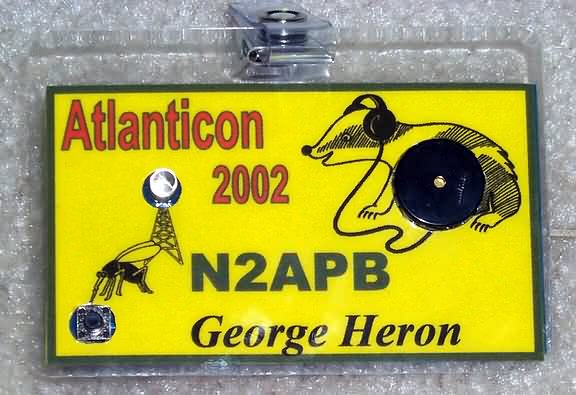
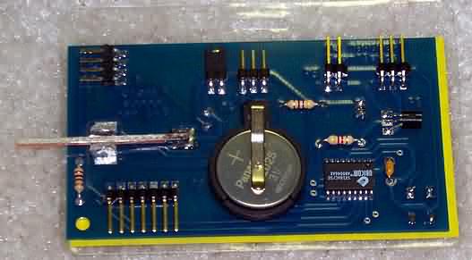
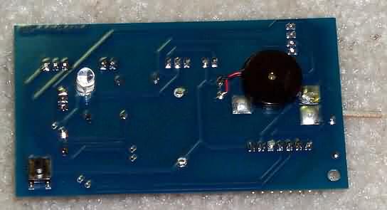
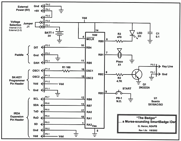
Morse-Annunciating SmartBadge In previous "Spotlight" installments of this column Ive described the simple, fast and inexpensive SX microcontroller from Ubicom (formerly Scenix) in the form of the PSK31 Audio Beacon project. Then later in the pages of NorCals QRPp magazine I overviewed the design of another SX project, the serial logging frequency counter, using that same chip and board. Hoping that QRP readers find these SX-based projects interesting and quite reproducible, I present this time a unique application of this PIC-like microcontroller in the form of a Morse-annunciating callsign badge. The Badger, as it is called, consists of a piezo sounding device and a SuperBrite LED on the front of the pc board, and a small pushbutton that is used to start the beeping and blinking of the owners callsign. An SX-18 microcontroller and several other components also reside on the board which is overlayed with a custom-designed laminated callsign badge. A 3V lithium battery is provided on the pc board, allowing the annunciating badge to be operated free of an encumbering heavier battery. Add a common badge clip and the Badger can be worn at club meetings and other ham radio events to the amazement of everyone! FEATURES Badge size - pcb is 2" x 3.5", laminated overlay is 2.5" x 3.5"; Piezo - approximately 4 kHz, adjustable for peaking to individual unit; LED - a red SuperBrite LED Pushbutton - micro-size, initiates annunciating sequence; Annunciation - piezo and LED are modulated using Morse code at given speed to announce callsign and other features; Key/Paddle - pads on pcb are provided for builder to add a miniature, on-board homebrew key or paddle, and signals provided off-board via 3-position pin header connection; Keyline output - buffered output line delivers Morse to external transmitter via 2-position pin header connection; Expansion connector - provides access to special functions (described later herein), accessible by 7-position pin header; Programming connector - 4-position pin header connector allows user to connect the SX-Key or SX-Blitz programming tool for custom programming of the SX micrcontroller chip. Operating modes - annunciate callsign via piezo and/or LED, repetitive "beacon mode", iambic keyer, keyer speed adjust, piezo tone adjust and straight key tone oscillator; 3V lithium battery - standard watch battery provides circuit power . SX chip "sleeps" during quiet times, ultimately providing infrequent need for battery replacement. HARDWARE Refer to Figure 1 for the following discussion. The SX-18 microcontroller contains the software program that provides all the features of this project. Clocking for this chip is provided by an on-chip RC oscillator. Timing accuracy of the tones frequency and the Morse code speed is not overly critical so we can live with slight chip-to-chip variations in clocking rates when using the built-in oscillator mode - this is a nice price to pay for reduced parts count! Power is normally provided by an onboard 3V lithium battery when Jumper J1 is in place as shown, or by an external 5V source when J1 is in the pin 2-pin 3 position on pin header P3. External 5V is required only when a new program is being burned into the SX chip. This "in-circuit programming" capability of the SX device makes it very easy to re-use in projects. When the Badger smart badge is quiet, the SX controller is "asleep". In this state, the SX clock oscillator has stopped and the chip only draws several microamps of current from the 3V battery. However when the smart badge is triggered by pushbutton PB-1 being actuated, the SX chip wakes up and begins executing its internal software program. Turning the smart badge on by means of a quick tap is reminiscent of the activation scheme for the communicator worn on the shirt in the old Star Trek series ... "Beam me up Scottie!". Once triggered, the program in the SX chip wiggles the output bit RB1 at about a 4 kHz rate, causing piezo device X1 to emit a reasonably loud tone. The software program modulates the tone with Morse code at about 15 wpm rate to sound the owners callsign. The RB2 output pin is also turned on and off at the same Morse code rate and buffered by transistor Q1 to drive the KEY input of a transmitter. In this way the Badger can key a transmitter, which will be seen as a more useful feature when we describe some other Badger features in a moment. LED D1 is also turned on and off according to the Morse code being sounded, giving visual indication of the callsign being announced. The blinking SuperBrite LED is very useful in helping to one copy the Morse code. The specs for the piezo state that the sound pressure generated (i.e., audio output level) is at least 80 dB, which is pretty easy to hear in a typical environment. However when the room is filled with talking people and other noise, the beeping can easily be drowned out. Thus LED blinking in time with the sounding of the piezo greatly helps by correlating visual and audible inputs to person trying to copy the callsign. Paddle inputs are available for connection of a standard iambic paddles, enabling the SX chip to perform as a keyer. When the smart badge is placed into "keyer mode", grounding of the dit or dah input lines (SX ports RB4 or RB5, respectively) activates the piezo and LED for the corresponding dit or dah time periods. Another related mode, Straight Key mode, instructs the SX program to recognize grounding of the dah input pin as a straight key closure, which in turn sounds the piezo and turns on the LED. The Badger pc board was layed out to allow the builder to construct a miniature homebrew paddle right on the back of the smart badge. As shown sticking out on the left of Figure 2, a thin strip of pcb material is soldered in between two grounding stubs such that when the strip is moved from side-to-side by the operators hand, the Badger sounds off just like a code practice oscillator. Additionally, when pin header P5 connected to a transmitter, the smart badge acts as a full-fledged iambic keyer. Captain Kirk never had it this good! The pc board was designed to use a surface mount version of the SX-18 microcontroller. This package was selected over a DIP package because of its lower cost, lower profile and lighter weight. Even the pc board was fabricated using .031" material, providing for a lighter weight badge hanging on ones shirt pocket. Because we used a surface mounted SX chip, we needed to provide the means to initially program the chip after it was soldered in place, and for reprogramming the chip when a different or improved program is ultimately available later on. The 4-position pin header P1 is provided in order to allow the SX-Key or the SX-Blitz programmers to connect to the board and feed new software to the SX chip. This connector and in-circuit programming function will not normally be used by most people - only when a new program is desired for the chip. SOFTWARE The software design is based around a recurring interrupt, which is set to happen every 148us when the RTCC counter (which counts clock cycles) rolls around past zero. This is a common way for PICs and SX chips to generate a constant stream of interrupts and is determined by a setting of the RTCC reload value at the end of each interrupt. Thus whatever operations done during the interrupt service routine (ISR) happen at that 148us periodic rate. As it turns out, generating the frequency for the piezo sounding device is the highest priority for the program and we toggle the bit connected to the piezo every time we pass through the ISR. Since a "cycle" of wiggling this bit takes two passes through the ISR (bit set on one pass, bit reset on the next), the basic default frequency of piezo operation is 2 x 148us = 296us, which sounds the piezo at 3.37 kHz. If we programmatically modify the RTCC reload value, the piezo tone will vary around that default frequency and the operator could "calibrate" the piezo output for its natural peak resonance. That is actually the operation done in the Calibrate mode of the software. Once in that mode, when the operator taps the pushbutton two times, the software reduces the RTCC reload value a bit and the resultant ISR rate (and the piezo frequency) is increased. When the operator taps the pushbutton once, the RTCC value is increased, which lengthens the interrupt rate and lowers the piezo tone. The rest of the Badgers program is really quite elementary and standard, as done by many of the PIC keyer chips/programs available today. We first determine the ASCII character of each letter in the pre-programmed callsign, use a look-up table (LUT) to turn it into an equivalent pattern of 1s and 0s that represent the characters dits and dahs, and the control the length of the piezo "beeps" and the spaces in between those beeps based on the dit and dah sequence. A default 10ms element of time is used as the Morse unit - a dah is 3 units with the piezo tone on, a dit is one unit, a character space is one unit with the tone off, and a word space is 3 units. Put all these unit tones and no-tones together according to the Morse-equivalent of the ASCII character and you have Morse code beeping and blinking at you at about 12 wpm! Timing of the Morse output is easy to adjust, via the "Morse Speed" mode settings. When this mode is entered, the basic default unit length is increased or decreased slightly, effecting a corresponding decrease or increase of the Morse output speed. Once the desired tone frequency and Morse speed selections are made, the software saves the settings in its onboard RAM memory. These settings are retained even during the sleep modes of the processor, and as long as the battery is not removed the settings will remain intact. If, however, the battery is removed or replaced, it will be necessary to perform the Badger calibration steps again. OPERATING MODES Mode selection is made by actuating the pushbutton at the end of the callsign annunciation sequence. When pushbutton actuation is detected, a series of Morse letters are annunciated, each signifying a specific mode. When the operator hears the desired mode letter, the pushbutton is depressed and that mode of operation is entered. The modes are described below according to their assigned letter. Mode A -- Normal Mode B -- Beacon Mode C -- Calibrate Mode D -- Iambic Keyer Mode E -- Morse Speed Adjust Mode F -- Straight Key Mode G -- Piezo Only Mode H -- LED Only Mode I -- Both Piezo and LED CONSTRUCTION Figure 2 shows the back side of the Badger. Note that the various pin header "options" have all been populated, and that a miniature paddle was fabricated on the left side of the smart badge. The 3V lithium battery is held in place via a clipped socket in the center of the board, and the surface mount SX microcontroller is just to the ight of it. Its hard to see it in this photo but there is a piece of clear acetate glued over top the components on this back side of the Badger, protecting it from possible shorts when worn. Figure 3 shows the front side of the Badger pc board, with laminated badge removed. Only three components are mounted on this side: the pushbutton (left), LED (middle) and the piezo (right). The laminated badge with corresponding holes slips over the components and is glued to the surface of the board. One is also able to homebrew the Badger from scratch using a piece of perf board, for example. A personalized programmed DIP version of the SX-18 is also available from the NJQRP for this case. SUMMARY BADGER
NOTES 2) A basic Badger kit is available from the NJQRP Club. Contains electronic parts, pc board, personalized pre-programmed SX chip soldered to the pcb, and laminated callsign badge and badge clip. Price is $18 and includes shipping to US and Canada. (DX orders add $5.) Pay using PayPal to n2apb@amsat.org, or write check/MO payable to "George Heron. N2APB" and send to 2419 Feather Mae Ct, Forest Hill, MD 21050.
Page last modified:
May 20, 2002
|