SNAP RF Probe & Power Measurement
|
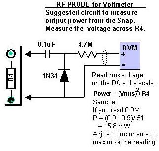
The RF Probe circuit above was taken from the ARRL Handbook 2000, page 26.11. This circuit will read pretty close to the RMS value of the voltage. The RF detector circuit has built-in scaling to give approximate RMS readings for sine wave signals. An ordinary diode detector outputs the peak value of a sine wave. To convert the reading to RMS one needs to multiply it by .707.
In the diode detector used in the RF Probe of the SNAP package, this scaling is done using a resistive voltage divider. If the DVM or voltmeter has an input resistance of 10 megohms (most do these days), a voltage divider is formed by the series 4.7 meg resistor in the RF probe and the DMM resistance. This ratio is 10/(10+4.7) or .68 which is less than 5% from .707. For a simple circuit this is probably close enough!
Return to the Atlanticon home page
![]()
![]()
![]()