SNAP Layout & Construction
|
Building the SNAP
Here are the details of putting this circuit together to make a working transmitter.
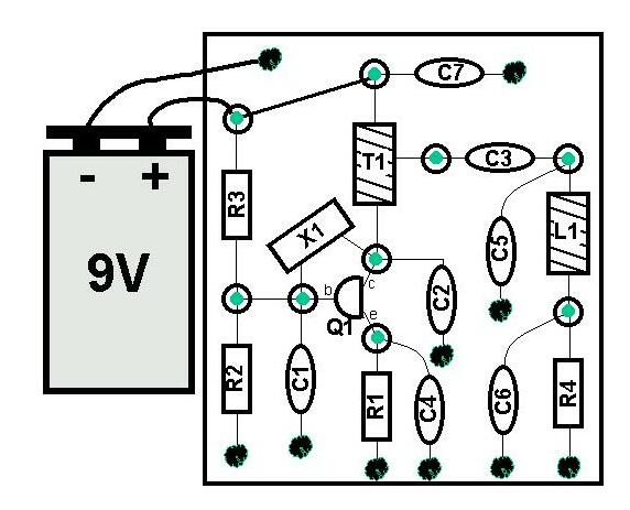
You can use the Board Layout diagram shown here as a guide to orienting your components on the pcb; however, it is only an example … you are encouraged to use whatever layout scheme you find convenient or preferable. Many homebrewers start with the "center" of the circuit and work outward, positioning components in a way that mimics the circuit schematic itself. Going about it this way allows you to easily relate between the schematic and hardware, thus aiding in making circuit measurements and tracking down problems.
Other homebrewers start at one end of the schematic (e.g., the output) and one end of the board, and work through the schematic adding one component at a time.
Some have indicated that they are going to use both sides of the board! They intend on mounting the oscillator components on one side and the output filter components on the other. Using this unique approach, they can mount the board vertically by soldering the edge of the board at right angles to a base piece of pcb material. This approach will end up with a board sticking up and accessible from both sides … pretty cool. This approach will surely get the attention of the judges at the Atlanticon building contest.
Actually, there’s nothing to say that you cannot use another (larger) piece of double-sided pcb material upon which to construct your transmitter. The "rules" for the judging that will occur at Atlanticon QRP weekend state that the exact component values must be used; but there’s no restriction on the size of the board they are mounted upon.
Construction GuideThe steps below are provided as a guide to constructing a Manhattan-style SNAP transmitter .
Clean the PCBYou should clean the copper-clad surface of the pcb material before gluing down the little pads and soldering component leads. Removal of oxidation and grease will ensure good connections.
You can clean the boards in several manners. The simplest, but perhaps least effective is to wash the board with soap and water, rinse and thoroughly dry. This will remove grease, but not too much oxidation.
In my opinion, the best way to clean the board is by lightly sanding the surface with "very fine" sandpaper or steel wool obtained at any hardware store. This will leave the copper surface shiny and free of oxidation, grease and other marks. You should then wash the board with soap and water to finish off the cleaning process.
There are some cleaning or polishing solutions that will also do an adequate job of preparing the copper surface for glue adhesion and soldering. We used Brasso to prepare the surface of the little mounting pads (done before punching them out of a larger piece of pcb material!). StayBrite is the name of another brand of polishing fluid. Just dab some onto a cloth, rub it onto the copper surface, buff it clean with a different area of the rag and you’re all set.
Glue the Manhattan Pads to the Board
The whole purpose of using little pads is to isolate the "node" (junction) of a component from the ground plane of the board. This standoff pad is a convenient way in which to electrically interconnect (solder) components, to physically mount components like IC sockets or variable capacitors, and to put isolated test points within the circuit to facilitate measurements.
The procedure for attaching a pad to the surface of the base board is quick, straightforward and simple. You’ll need to dab a small amount of SuperGlue (or another equivalent quick-setting adhesive) on the area of the board where you wish to put the pad. Then, using a pair of needle-nose pliers or tweezers, place the pad onto that dab of glue. I usually gently schmoosh the pad down onto the board. ("Schmoosh" is a technical term meaning to gently move the pad from side to side in order to ensure good glue contact on the underside.) Then apply direct downward pressure with the pliers for about 5 seconds. That’s it! The pad is now firmly in place, and as long as you don’t apply too much sheer pressure to it, it will stay in place for the duration.
Note: Be sure not to get any adhesive on your fingers or tools. It’s not too friendly to human skin. You should also cap the adhesive tube in between applications so as to minimize inhaling the fumes.
As mentioned, you can follow any number of approaches to orient the components on the board. And similarly, you can glue down all pads at once, or glue them individually in place as you add components to construct the circuit. Either way, there’s something to be said about planning out the real estate usage of the board … think ahead!
Mount transistor Q1
Q1 is a 2N2222-class of transistor. The orientations of its pins are: emitter-base-collector, as seen while looking at the flat side of the black transistor body with its leads pointing downward. It may be helpful to bend the leads into a triangular orientation, and to put little 90-degree "feet" in the very ends of the leads. This allows you to easily solder the leads to the 3 pads previously glued down in a similar triangular pattern. This approach would result in the transistor standing in an upright position.
Mount resistors R1, R2, R3 and R4
Resistors are easy to mount Manhattan-style. Merely cut the leads to an appropriate length that spans the two pads you’ll be soldering them to (or between the pad and ground plane.) It’s a nice construction technique when the component is oriented in a rectilinear grid, positioned horizontally or vertically, and somewhat raised up off the surface of the board and pads – it looks neat, orderly and it facilitates easily probing with measurement leads (DVM or oscilloscope). But prettiness usually has absolutely nothing to do with how well a circuit operates, so it is often a builder’s choice on how much time is spent in positioning a component using this construction technique.
Mount capacitors C1-thru-C7
The 0.1uF axial lead capacitors of this project (C3, C4 and C7) are mounted in a manner similar to that of the resistors. The radial lead capacitors (C1, C2, C5 and C6) have round disc-like bodies and can be mounted "upright". As with most components, but especially so with capacitors, it’s usually important to mount the devices close to the other components in the circuit, thus minimizing stray capacitance and extraneous signal radiation.
It’s good to point out here that not all component leads need to be soldered to standoff pads. Oftentimes one leg of the component is grounded (as with 6 of the 7 capacitors in this project), and the builder can just solder the component lead directly to the ground plane of the base board. (Note: When soldering directly to the base board, more heat will be needed from your soldering iron due to the larger heat sink of the copper ground plane … be patient while soldering these leads.)
Prepare the L1 toroid inductor
This is a fun part of the project that homebrewers sometimes worry about. There’s actually nothing hard in winding a few turns of wire through the toroid core, and we’ll take you through it in a step-by-step manner.
Uncoil the supplied red magnet wire, cut off a 24" length and begin winding the wire around the T37-2 toroid core (one side of this little "donut" is red.) Count one turn each time the wire is passed through the core. You will be putting a total of 35 turns around the toroid core in this manner. Refer to the photo and figure below for guidance. I normally hold the toroid core in my left hand and weave the length of the magnet wire through the core in a sewing-like manner, pulling each loop tight against the body of the core and proceeding around the core being sure not to overlap any of the windings.
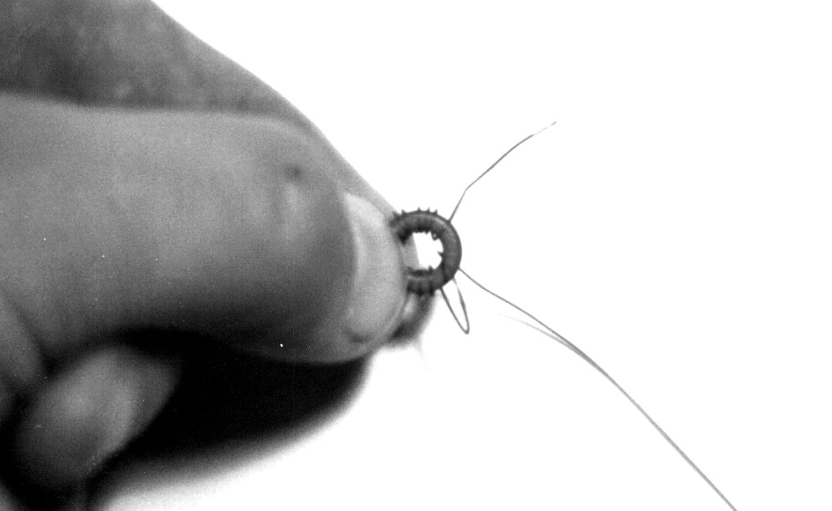
Fig 2: Holding the toroid core during winding
Fig 3: L1 after winding (only 17 turns shown)
Once the specified number of turns have been placed onto the core, trim each end of the wire to such that they each extend about ½" from the body of the toroid. Next prepare ends of the wire for soldering by using an Exacto knife or equivalent sharp-edged tool to scrape off the enamel coating. You can then tin the ends by pressing a hot soldering iron tip to them and applying solder. A careful job here will ensure a good connection to the pads of the circuit. Position L1 over the pads you have located on the board for this component and solder the leads to the two pads.
Fig 4: L1 mounted to pads
Prepare the T1 transformer
The T1 transformer is a "bifilar-wound" inductor, meaning that you’ll twist two magnet wires together and wind them at the same time. Take the remaining 12-inch length of red magnet wire (left over from winding L1), and loosely twist it together with the 12-inch length of green magnet wire supplied in the kit. These wires should roughly look like the diagram below below.
![]()
Fig 5: Red and Green Magnet wires used for T1
(Suggestion: You could clamp the ends of the wires in a vise and use a twist drill to wind the length of the wires together; but don’t make the twists too tight!)
Next wind the twisted wire pair around the FT37-43 toroid core (the black one) in the same manner as done previously for L1. See the diagram below for identification and nomenclature of the four leads you have after winding the toroid:

Fig 6: T1 after winding Red & Green Wires
You next need to form the "center tap" of the transformer by twisting together the a and b’ ends. These ends are easy to identify, using the red wire from the start of the toroid winding and the green wire from the end of the winding. Or vice versa … it doesn’t matter whether you use the a-b’ or the a’-b wires as the center tap. The transformer is symmetrical.
NOTE: If you don’t have two colors of magnet wires when making this transformer, but instead use two wires of the same color, it's a bit hard to know which ends to connect together for the center tap. You should use an ohmmeter to determine the proper ends. Remember to strip off some of the insulation on the ends before using your ohmmeter! Once you identify the proper ends of the wires a-a’ and b-b’, you can then twist wires a' and b together to form the center tap.
You’ll now have 3 wire ends for this transformer: two end wires and one combined wire in the center formed by twisting the two center ends together as described above. Trim all three wires to about ½" and prepare them in the same manner as with the ends of L1. (That is, scrape them and tin them with a soldering iron.) Holds the three transformer leads over the three standoff pads that have been previously glued down, and solder each lead to the top of a pad. The illustrations below should help.
Fig 7: T1 soldered to pads (showing centertap)
Return to the Atlanticon home page
![]()
![]()
![]()