SNAP Examples
|
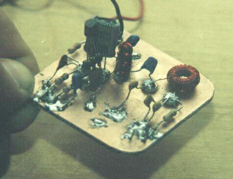
Shown above is a SNAP from the acknowledged Grand Master of
Manhattan-style construction: Jim Kortge, K8IQY. What a fabulous looking work of
art! (Note that Jim is one of the judges for the SNAP competition and his SNAP is
not eligible for any of the prizes.) There are several things to take note of in this SNAP
construction:
- the board is *very* nicely cleaned and polished ... what a nice appearance;
- the crystal case is grounded with an extra wire seen at the top of the case;
- there is a "power switch" consisting of a little jumper on the right side
of the board;
- machined socket pins are used to mount the transistor, allowing easy swap-out;
- nice tightly-wound toroids are standing up neatly;
- the component layout doesn't follow the schematic layout ... doesn't have to.
|
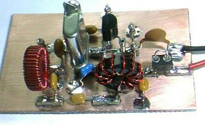
Above is a photo of N2APB's SNAP. Again, please note that this is only one example of a SNAP layout and construction ... and a rather plain vanilla one at that. Plus, no great pains were taken to make this an attractive rendition of the SNAP kit. In essence, this was the prototype upon which the entire project was based. Lots of experimentation, parts-swapping, and general molding of the circuit design happened on this workbench, yielding what we think is a relatively stable design.
Little touches worthy of bringing to attention:
- rounded corners of the pcb materialmake it nicer looking and less prone to sharp
and pointed edges;
- I used a 3-pin section of a machined pin IC socket to serve as a transistor
"socket", allowing me to easily swap transistors for test and evaluation;
- I used round Manhattan pads, as punched out with a Harbor Freight hand punch ...
very convenience, and attractive. (Clean the pcb material before punching out the
pads!)
- It doesn't matter most of the time if components stand up straight or if they are
layed down close to the pc board;
- My component layout looks just like the schematic layout, making it a piece of cake
to locate parts to probe, wiggle and substitute.
There are many other little "tricks" that the homebrewer will discover along the way ... that's what makes this the education and fun project that it is!
Another Example of a Manhattan-style Circuit
Take a look at the next photo representing a portion of the 2N2/40 circuit from Jim Kortge’s (K8IQY) web page (http://www.qsl.net/k8iqy/). Remember, the 2N2/40 project is one of the outstanding references for Manhattan-style construction technique. And by the way, Jim Kortge is not only attending Atlanticon and helping to judge the SNAP project entries during the Building Contest, but he is also one of the seven honored speakers making presentations that weekend … and Jim’s topic concerns the making of another project using Manhattan-style construction! Expert guidance, straight from the horse’s mouth!
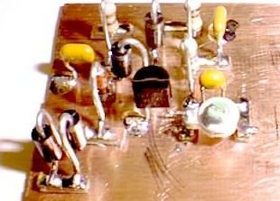
Fig 8: Portion of the 2N2/40 board
(Thanks to Jim Kortge, K8IQY for the photo)
Although Jim uses square pads (easier to construct on your own if you don’t have access to a punch), you can see that the Manhattan-style techniques are very similar to the descriptions in this SNAP kit.
Notice that the diodes and resistors are mounted in an upright manner, with the "top" lead bent over and down to be soldered to a pad right next to the bottom lead.
Notice the 2N2222A transistor with its emitter on the left soldered directly to the ground plane, and its collector on the right soldered to the trim capacitor being held up by the pads.
You can also see the capacitors mounted upright in a rectilinear fashion on the board, helping give the board an appearance of being a "little city".
Return to the Atlanticon home page
![]()
![]()
![]()