K8IQY 4017 Transverter
![]()
![]()
This page contains late-breaking news and other important information concerning the 4017 Transverter Kit from the NJQRP Club.
Additionally, as an extra benefit to kit owners, we present color versions of all the images contained in the Technical Reference Manual. We hope these photos and graphics will be of value to
KIT NOTES:
1) R1 Power Resistor in Input Attenuator -- R1 in the parts list is supplied as a 51-ohm, 1-watt carbon resistor instead of the 35-watt TO-220 package version. Using this 1-W resistor alone will force the user to limit power input from the 40m transmitter to less than 1-W. Substitute a suitably-higher power resistor (e.g., four 200-ohm, 1-watt resistors in parallel) in order to handle the rated input power from the transmitter. The builder will also need to provide a high-power R3 (3.3-ohm).
2) Heatsink for the Final -- A standard TO-220 style heatsink is provided in the kit as an alternative to the Manhattan-style pcb material heatsink for the 2SC1945 final transistor. Builder's choice!
3) Creating the Manhattan Pads -- Thin strips of pcb material are provided in order for the builder to construct the Manhattan pads. Using wire cutters (diagonals, side cutters, etc.) the builder should nip off 3/32" lengths of these strips to form the small pads that form the circuit nodes when glued to the base board. Enough material is provided to produce over 100 pads. (About 80 are needed.)
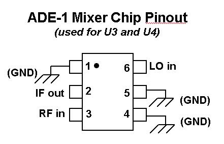
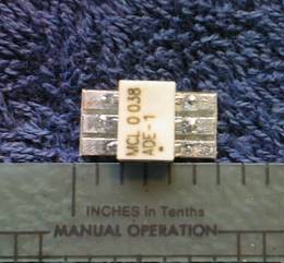
4) Making Sub-Board for ADE-1 Mixer Chip -- It will be necessary for the builder to construct a "sub-board" in order to mount the ADE-1 surface mount mixer IC's. This is not as hard as it might sound at first. Two pieces of 1/2"-square copper-clad boards are provided for this purpose (one for each of the mixers). The builder should score the surface into six segments as shown in the manual photos and below. The chip is then soldered to these makeshift pads, and the sub-board is glued to the main base board where required. Wires and component leads may then be soldered to the sub-board pads in a normal Manhattan-style fashion.
5) Wiring in the ADE-1 Mixer in place of LMX-113 -- As mentioned in the text of the manual, we supplied a less expensive alternative called the "ADE-1" for the U3 and U4 mixers. But what we neglected to mention was that the pinout for the ADE-1 is different from that of the LMX-113 and it would take some detective work to determine the correct wiring. (Complicating matters slightly, there was an error in the ADE-1 package diagram in the "Handiman's Guide to DB Mixers" at the end of the manual.) Okay ... here's the correct package pinout for the ADE-1 mixers:
6) Parts List Typos -- No parts errors actually, just some "quantity" number corrections to keep you from looking for some parts not really there. (Reference designators were switched around at the last minute and the QTY column wasn't adjusted afterwards.) Four lines are affected, as follows:
Item 11 should read qty 4
" 32 " " " 2
" 38 " " " 3
" 40 " " " 3
7) C-35 on the Rx Converter layout -- C53 across D-8 in the Receive Converter schematic is shown (incorrectly) as C-35 on the board layout.
IMAGES FROM THE TECHNICAL MANUAL:
Block Diagram
Attenuator:
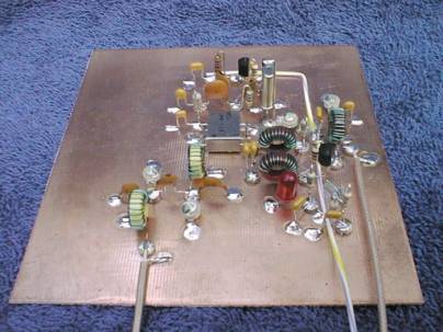
Receive Converter:
Frequency Response of the input filter:
Frequency Response plot of the diplexer:
Transmit Strip Schematic:
Output Filter Frequency Response:
Manhattan-style mounting technique for the ADE-1 mixer:
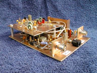
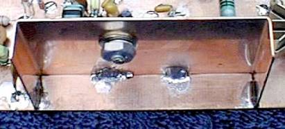
Final assembly:
Receive Converter:
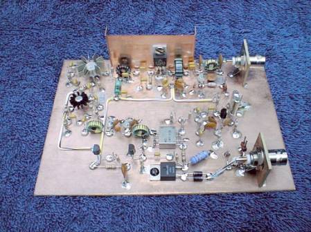
TR1/TR2/Attn/RFSwitch/Transmit Strip:
Heatsinking the Final Output Stage:
Spectral Purity:
![]()
![]()
![]()